Evac Evacinclick 1 User manual

5435261 Membrane box
5435259 Flush valve
5435265 Flush valve housing
EvacInclicks 1, 2 and 3 on the right replace
products on the left. EvacInclick 1
5350000
EvacInclick 2
5350020
EvacInclick 3
6542341
EVAC reserves the right to make alterations to this specication without prior notice.
© Copyright Evac Oy. All rights reserved.
CUSTOMER SUPPORT
Date: Doc.
VACUUM TOILET
2
evacinclickS 1, 2 anD 3 FOR iFö TOileTS
11 Apr 2011 9:00015G

29 Nov 2010 9:00062E
EVAC OY, tel.: + 358 20 763 0200, Finland
Table of contents
Installation:
P/N 5350000 EvacInclick 1...................................................................................................... Doc no. 2:01009E
Spare parts:
P/N 5350000 EvacInclick 1...................................................................................................... Doc no. 6:01117E
P/N 5350000 evaciNclick 1
PRODUCT INFORMATION DOCUMENT, P/N 5824850
EVAC reserves the right to make alterations to this specication without prior notice.
© Copyright Evac Oy. All rights reserved.
CUSTOMER SUPPORT
Date: Doc.
1

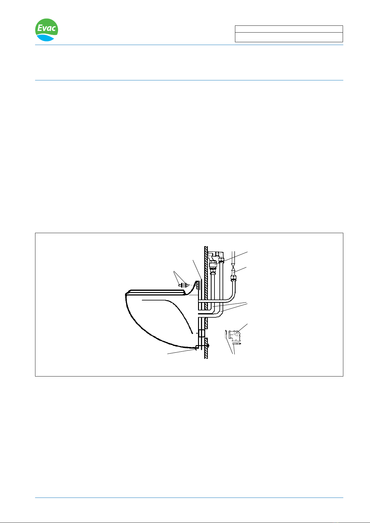
FLUSH CONTROL UNIT
5350010
Bowl mounted push button
! NOTE: A riser pipe after the toilet or the Super Silent
Toilet may require a prolonged ushing time. Change
nozzle Blue 40 to White 30 or Yellow 20.
( See spare part doc. 6:01117E )
To discharge
valve
Vacuum inlet
Water supply
Fig.1
EVACINCLICK 1
Water supply
P/N 5350000 is replacing P/N 43525.9, 43526.0, 43526.5, 5435259, 5435261 and 5435265
EVAC reserves the right to make alterations to this specication without prior notice.
© Copyright Evac Oy. All rights reserved.
installation
Date: Doc.
VACUUM TOILET
1
5350000 EVACinCliCk 1
05 Jun 2013 2:01009E
When installing the EvacInclick 1, execute the applicable procedures in the given order:
1. Vacuum toilet removal
2. Vacuum toilet disassembly
3. Vacuum toilet reassembly (including installation of the EvacInclick 1)
4. Vacuum toilet re-installation
1. Vacuum toilet removal
Refer to g. 2
1.1. Shut off the fresh water supply and ush the toilet to empty the bowl. Disconnect the external 1/2” water supply
line from the side of the toilet, or disconnect the water supply hose connected to the back of the toilet.
1.2. Remove all hardware that secures the toilet to the wall or the oor.
1.3. Loosen the hose clamps, remove the rubber elbow or coupling from the sewage outlet port of the toilet, and
insert the tapered end of the elbow (or suitable plug) into the vacuum pipe opening to prevent the vacuum
loss.
Fig. 2
Fresh water supply pipe
Mounting hardware
Vacuum breaker
Water hose
Rubber elbow
Hose clamp
Wall seal
! NOTE: Some older models may be xed
to the wall with an extra xing hook.
EVAC reserves the right to make alterations to this specication without prior notice.
© Copyright Evac Oy. All rights reserved.
installation
Date: Doc.
VACUUM TOILET
2
5350000 EVACinCliCk 1
05 Jun 2013 2:01009E

2. Vacuum toilet disassembly
Refer g. 3
2.1. Remove the attaching screws from the mounting plate console and then remove the seat.
2.2. Remove the back cover by unscrewing the wing nuts from the fastening rods (if present).
2.3. Separate the two vacuum hoses with the non-return valves from the discharge valve and the outlet pipe.
2.4. Unscrew (turn counterclockwise) the toilet ush knob´s connecting rod from the ush valve rod and lift the
connecting rod up to gain access to the ush valve fastening screw.
2.5. Disconnect and remove the water connecting pipe assembly from the ush valve.
2.6. Remove the fastening screw and pull the ush valve out past the guide peg to remove it.
2.7 Recommendation: Inspect the discharge valve, and especially the rubber parts. Replace if necessary.
(Always clean the porcelain surface that touches the discharge valve before re-installing.)
Fig. 3
Wing nut
2) Flush knob removal
1) Seat removal
3) Flush valve removal 4) Recommended discharge valve inspection
Vacuum
hose
Optional plate in
some installations
Rubber parts
Vacuum
hose
Water con-
nection
Discharge valve
Flush valve rod
Screw for
mounting
plate
Pull knob
Plastic bushing
Connecting rod
Check and clean
sealing surfaces
EVAC reserves the right to make alterations to this specication without prior notice.
© Copyright Evac Oy. All rights reserved.
installation
Date: Doc.
VACUUM TOILET
3
5350000 EVACinCliCk 1
05 Jun 2013 2:01009E

3. Vacuum toilet reassembly
During this procedure refer to g. 4 and 5.
3.1. Install the toilet push button.
3.1.1. Check to see that the hole in the porcelain is circular. If not, le the hole to the proper size, so that the
push button moves freely.
3.1.2. Position the lower part of the push button assembly in the porcelain.
3.1.3. Install the upper parts of the push button assembly through the hole in the porcelain.
3.1.4. Secure the push button assembly in position with the locking pin.
Bowl mounted push button
Fig. 4
Upper part of push button
Locking pin
Lower part of push button
3.2. Attach the water connection hose to the water valve inlet and install the push button hose into the ush
control unit.
3.2.1 For units with a water connection through the back and a USPH vacuum breaker, disconnect the hose from
the water valve outlet. Remove the elbow from the hose. Connect the vacuum breaker inlet hose to the
water valve. Insert the elbow into the vacuum breaker outlet hose and connect the other end of the elbow
to the ush ring.
3.2.2 For units with a water connection through the back and that not have a vacuum breaker, insert the elbow
on the end of the hose from the water valve outlet to the ush ring.
3.2.3 For units with a side water connection, remove the connector and cut off the tubing, leaving a tube length of
approximately 20 mm. Install the side water connector. Attach the elbow to the end of the water connection
hose. Connect one end of the water connection hose to the water valve inlet on the ush control unit, and
connect the end with the elbow to the side connection.
EVAC reserves the right to make alterations to this specication without prior notice.
© Copyright Evac Oy. All rights reserved.
installation
Date: Doc.
VACUUM TOILET
4
5350000 EVACinCliCk 1
05 Jun 2013 2:01009E

3.3. Attach the ush control unit bracket (with an attached control mechanism and a water valve) to the toilet
bowl assembly.
3.3.1 For units with a toilet mounted push button, position the ush control unit bracket inside the toilet bowl’s
body and align it with the holes in the porcelain. The ush control valve bracket is installed above the two
tabs on the push button bracket. Assemble the attaching screws through the hole in the seat and into the
ush control valve bracket.
! NOTE: For units using alternate methods for attaching the lid and seat assembly, consult the factory.
! NOTE: The hose with the non-return valve is to be pushed in the outlet pipe.
3.4. Carefully push the two vacuum hoses with the non-return valves onto the discharge valve and the outlet
pipe.
3.5. Install the back cover and secure it by screwing the wing nuts onto the fastening rods, if applicable.
Toilet mounted push button (top)
Toilet mounted push button (bottom)
Wing nuts
Vacuum hoses
Flushing ring
Fresh water supply
Fastening rods
Vacuum breaker USPH
(optional)
Outlet hose
Inlet hose
Elbow
Flush control unit bracket
Fig. 5
Water valve
Control mechanism
Flush control
unit
EVAC reserves the right to make alterations to this specication without prior notice.
© Copyright Evac Oy. All rights reserved.
installation
Date: Doc.
VACUUM TOILET
5
5350000 EVACinCliCk 1
05 Jun 2013 2:01009E

4. Vacuum toilet re-installation
During the following procedure, refer to Figures 2 and 3.
4.1. Inspect and ensure the repaired toilet is free from obvious signs of damage or wear.
4.2. Inspect the gasket or edge strip between the toilet and mounting surface, and replace if necessary.
4.3. Align the toilet mounting holes against the bulkhead.
4.4. Install the rubber elbow or connector to the sewage piping and the toilet’s outlet. Do not tighten the hose
clamps at this stage.
4.5. Re-install mounting hardware to secure the toilet to the bulkhead.
! NOTE: Exercise caution when installing the vitreous china toilet. Do not over tighten nuts or damage
may result.
4.6. Tighten both hose clamps on the discharge rubber elbow or connector.
4.7. Reconnect the customer water supply.
4.8. Turn on the toilet’s water supply.
4.9. Flush the toilet and check all joints for vacuum and water leaks.
EVAC reserves the right to make alterations to this specication without prior notice.
© Copyright Evac Oy. All rights reserved.
installation
Date: Doc.
VACUUM TOILET
6
5350000 EVACinCliCk 1
05 Jun 2013 2:01009E

02 Oct 2013
5350000 EVACINCLICK 1, FLUSH CONTROL UNIT FOR IFö TOILETS
5350010
Push button, complete
5774002
Water valve
5523200
Spring
6542246
Clip
5820900
Elbow
5503906
Hose
5470202
Hose
5775500
Control mechanism
5350004
Locking pin
5350001
Bracket
5433217
Water connection
hose
5430164
Elbow
5433281
Hose with
Mini-check valve
5470214
Hose
Alternative nozzles:
P/N 5778000, White 30
P/N 5778004, Yellow 20
5959902
Mini-check valve
6542246
Clip
6:01117E
5481100
Hose
EVAC reserves the right to make alterations to this specication without prior notice.
© Copyright Evac Oy. All rights reserved.
Spare partS
Date: Doc.
VACUUM TOILET
1
This manual suits for next models
8
Table of contents
Popular Plumbing Product manuals by other brands

Weka
Weka 506.2020.00E ASSEMBLY, USER AND MAINTENANCE INSTRUCTIONS

Kohler
Kohler K-6228 Installation and care guide

UBERHAUS DESIGN
UBERHAUS DESIGN 75175017 Operator's manual

American Standard
American Standard DetectLink 6072121 manual

Uponor
Uponor Contec TS Mounting instructions

Pfister
Pfister Selia 49-SL Quick installation guide


Kohler
Kohler Centerset K-15240 Homeowner's guide

Viega
Viega Prevista Dry 8522.33 Instructions for use

Sanela
Sanela Lema SLP 59RB Instructions for use

Elkay
Elkay EDF15AC Installation, care & use manual

Hans Grohe
Hans Grohe AXOR Citterio E 36702000 Instructions for use/assembly instructions

baliv
baliv WT-140 manual