Esser 8000C User manual

Operation and Installation Instruction
Fire Alarm Computer
8000C / M

Page 2 Fire Alarm Computer 8000C / M
Intended purpose
This product must only be used for the applications outlined in the catalogue and the technical
description and in combination with external components and systems which have been
approved or recommended by ESSER.
Warning
In order to ensure correct and safe operation of the product, all guidelines concerning its
transport, storage, installation, and mounting must be observed. This includes the necessary
care in operating the product.
Safety-relevant user information
This manual includes all information required for the proper use of the products described here.
The term 'qualified personnel' in the context of the safety information included in this manual or
on the product itself designates:
•project engineers who are familiar with the safety guidelines concerning fire alarm and
extinguishing systems
•trained service engineers who are familiar with the components of fire alarm and
extinguishing systems and the information on their operation as included in this manual.
•trained installation or service personnel with the necessary qualification for carrying out
repairs on fire alarm and extinguishing systems or who are authorised to operate, ground
and label electrical circuits and/or safety equipment/systems.
Safety warnings
The following information is given in the interest of your personal safety and to prevent damage
to the product described in this manual and all equipment connected to it.
Safety information and warnings for the prevention of dangers putting at risk the life and health
of user and maintenance personnel as well as causing damage to the equipment itself are
marked by the following pictograms. Within the context of this manual, these pictograms have
the following meanings:
!Danger of death, severe injury or considerable material damage if the relevant safety
precautions are not observed.
☞Important information on the product or a particular section of this manual, which
should be read with particular attention.
Safety

Fire Alarm Computer 8000C / M Page 3
1 General ....................................................................................................................................................4
2 General view............................................................................................................................................5
2.1 Key switch / enabling operation ............................................................................................................6
2.2 Function of the display and operating elements ..................................................................................7
3 Operating status of the fire alarm control panel...................................................................................16
3.1 Normal condition..................................................................................................................................16
3.2 Fire .......................................................................................................................................................16
3.3 Trouble .................................................................................................................................................17
3.4 CPU failure...........................................................................................................................................17
3.5 Disconnection ......................................................................................................................................18
3.6 Testmode .............................................................................................................................................18
4 Operation ...............................................................................................................................................19
4.1 Function keys / selection menu ..........................................................................................................19
4.1.1 Display / display control................................................................................................. 21
4.1.2 Display priority of the messages in the display ............................................................. 23
4.1.3 Info text / additional text and parameter display............................................................ 24
4.2 Entering time/date ...............................................................................................................................25
4.3 Detector zones.....................................................................................................................................26
4.3.1 Switching on / resetting a detector zone ....................................................................... 26
4.3.2 Disconnect a detector zone........................................................................................... 27
4.3.3 Status of a detector zone .............................................................................................. 28
4.4 Detectors..............................................................................................................................................29
4.4.1 Switching on / resetting a detector ................................................................................ 29
4.4.2 Disconnect a detector.................................................................................................... 30
4.4.3 Status of a detector .......................................................................................................31
4.5 Controls................................................................................................................................................32
4.5.1 Switching on a control output ........................................................................................ 32
4.5.2 Disconnect a control output .......................................................................................... 33
4.5.3 Status of a control output .............................................................................................. 34
4.6 Common display of the status messages ..........................................................................................35
4.7 Delay and Verify ..................................................................................................................................36
4.7.1 Delay ............................................................................................................................. 37
4.7.2 Verify ............................................................................................................................. 37
4.8 Alarm counter ......................................................................................................................................38
4.9 Lamp test .............................................................................................................................................39
5 Service Level .........................................................................................................................................40
5.1.1 Primary loop functions................................................................................................... 41
5.1.2 Sensor functions (loop) ................................................................................................. 43
5.1.3 Sensor functions (zone/detector) .................................................................................. 45
6 Installation Instruction............................................................................................................................47
12 Micromodule....................................................................................................................................... 107
24 Commissioning / Servicing ................................................................................................................ 145
Table of Contents

Page 4 Fire Alarm Computer 8000C / M
1 General
To equip buildings, facilities, commonly-frequented areas and working spaces with a fire warning
system can only be carried out economically and with reasonable propriety when correspondingly
well-founded safety concepts are developed and accordingly applied.
Wherever the highest requirements are made on a fire warning system, whether in small
commercial facilities or in industrial plants, the Fire Alarm Computer 8000C / M transforms safety
techniques and economy into practical reality. The modular design with different micro modules
and individual extension concepts allow the Fire Alarm Computer 8000C / M to be easily adapted
to special requirements. The Fire Alarm Computer 8000C / M represents the most modern
standard of fire warning technology. A reliable fire warning facility is guaranteed by the application
of "intelligent" fire detectors connected in an analog loop which is tolerant to short and open
circuits.
In this analog loop - the esserbus®/ esserbus®-PLus - up to 127 loop devices each capable of
being configured into 127 individual detector zones can be connected with an overall cable length
of up to two kilometres. The esserbus®is a two-wire line supplied and monitored at both ends in
ring topology. The Fire Alarm Computer 8000C / M automatically registers the wiring of the analog
loop and determines the logical addresses of the individual loop devices. A separate adjustment of
the addresses of the individual loop devices is unnecessary. Bei Systemen mit der esserbus®-
PLus Ringleitung ist zusätzlich der direkte Anschluss von adressierbaren, busfähigen
Signalgebern möglich. Für diese, direkt über den esserbus®-PLus angesteuerten Signalgeber, ist
keine weitere Spannungsversorgung erforderlich.
Subscribers in the esserbus®are automatic and non-automatic intelligent fire detectors, technical
alarm modules (TAL) and the specially developed esserbus®transponder input/output devices.
These esserbus®transponders are loop devices with freely programmable inputs and outputs, for
example for the activation and monitoring of external devices such as display panels, alarm
devices, door closers and other connected equipment.
Using the essernet®safety network, 31 Fire Alarm Computer 8000C / M or other network
subscribers such as display and operating panels or alarm devices can be connected in a
homogenous network. Operation of the fire warning system, e.g. switching off a detector zone, is
possible from any fire alarm control panel or operating panel in the essernet®. Signals such as
alarm, trouble, disconnection or other events are transferred to all subscribers in the essernet®and
can be accessed from any desired position. Data exchange can, according to the transfer rate, be
carried out either with a twisted pair or a LAN cable. The essernet®communications protocol
guarantees reliable data exchange even if a short or open circuit occurs in the network.
These Operating Instructions are intended to aid you in the operation of the Fire Alarm Computer
8000C / M in addition to the description provided by the specialised installer and should be kept
together with the technical documentation of the fire alarm system. If you have any questions,
please consult your specialised installer.
The operation of an installed and operative fire alarm control panel may only be carried out by
authorised and trained persons under observance of the safety precautions and, if necessary, in
collaboration with other organisations (e.g. fire department).
General

Fire Alarm Computer 8000C / M Page 5
2 General view
locked
unlocked
Master Box (MB)
Delay
Verify
in Operation
CPU Failure
Relay Outputs
Master Box
Testmode
Fire Pre-Alarm Trouble Disconnection
Notify Fire Dept.
Delay
Panel
reset
Disconnect
Master Box
Verify
Buzzer off
Additional
Messages
Disconnect
Relay
On
Off
Test
Status
Zone
Detector
Relay
123
456
789
0
Releasing System
1 5432
9
8
7
6
Fire alar m
Disconn. / Trouble
Fire alar m
Power Supply
Disconn. / Trouble
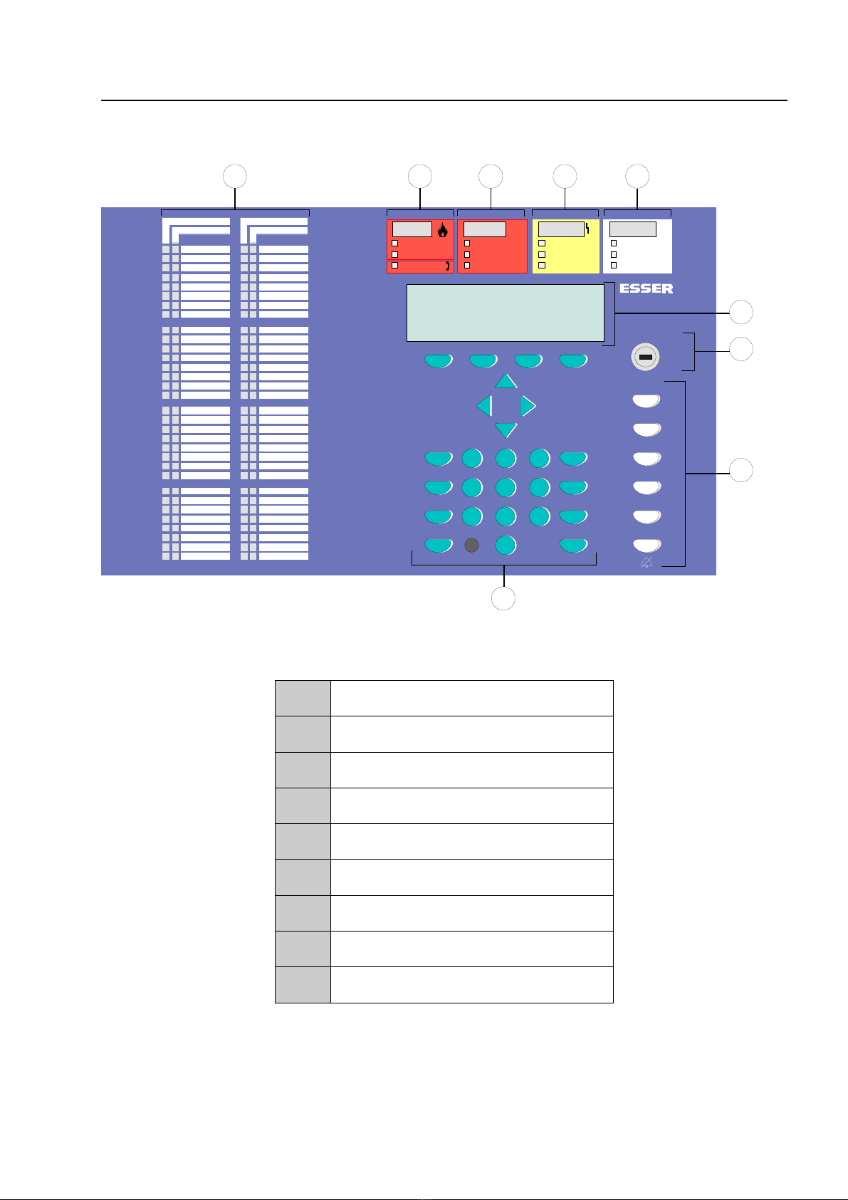
Fig. 1: General view of the display and operating elements
1Single zone indicator units (GEA)
2Common display FIRE
3Common display PRE-ALARM
4Common display TROUBLE
5Common display disconnection
6Alphanumeric display
7Key switch
8Operating elements
9Function keys and keyboard
General view

Page 6 Fire Alarm Computer 8000C / M
2.1 Key switch / enabling operation
Key switch in horizontal position
locked
unlocked
Fig. 2: Keyboard unlocked
♦The keyboard is unlocked for the operation of the single Fire Alarm Computer 8000C / M and
other processors interconnected through the essernet®.
♦The display menu is activated.
♦If a fire alarm is activated, the activation of the master box (MB) is inhibited. (Works
adjustment - can be changed by client programming.)
!In case of a fire alarm, activation of the master box (MB) will be disabled by the FACP.
The fire brigade will not be alarmed, automatically. In case of an event, the red LED Notify
fire department will be lit.
Key switch in vertical position
locked
unlocked
Fig. 3: Keyboard blocked
♦The keyboard is blocked. The key can be removed.
♦The keys Additional Messages and Verify / Buzzer off can still be operated when the keyboard
is blocked.
Key switch / enabling operation

Fire Alarm Computer 8000C / M Page 7
2.2 Function of the display and operating elements
The Display System 8000 is available with standard and ¼-VGA-Display.
On
Off
Test
Status
Zone
Detector
Relay
123
456
789
0
3
4
2
1
4
2
1
123
456
789
0
3
Fig. 4: Operating elements - keypad - display Operating elements - keypad - 1/4 VGA display
1Alphanumeric display
standard or ¼ VGA display
2Menu
3Function key
4Cursor key
All received signals such as fire, trouble or switch-off are shown in the alphanumeric display in
alphanumeric form (8 lines, 40 characters per line).
Keyboard
By means of the key switch, the keyboard is unlocked for operation. With these keys, it is possible
to control panel functions such as switching detector zones and detectors on and off.
Function keys
With the four function keys, the menu options positioned above them in the alphanumeric display
are selected. Depending on the current state of the fire alarm control panel or the operation level,
differing menu options are shown in the display.
Function of the display and operating elements

Page 8 Fire Alarm Computer 8000C / M
Master Box (MB)
Fire
Notify Fire Dept.
Releasing System
Fig. 5: Common display fire
The common display Fire is activated if at least one fire alarm has been detected. The originating
detector or detector zone will be shown on the alphanumeric display.
☞If evacuation plans or guidelines exist for cases of fire alarm, these plans have to be
followed and the premises have to be evacuated, if necessary. Make sure to inform yourself
well in advance about existing escape routes and required measures in case of a fire.
Fire
Red LED is permanently on ⇒Fire alarm !
At least one detector and / or one manual call point and / or a
loop is signalling a fire condition.
Fire Releasing System
Red LED is permanently on ⇒The fire releasing control equipment is been activated.
Master box (MB)
Red LED is permanently on ⇒The master box (MB) is activated and the intervention staff
(e.g. fire department) has been alarmed.
Notify fire department
Red LED is permanently on ⇒The master box (MB) has malfunctioned or is switched off and
cannot be activated. Call the fire department immediately !
Function of the display and operating elements

Fire Alarm Computer 8000C / M Page 9
Delay
Verify
Pre-Alarm
Fig. 6:Common display pre-alarm
In the Pre-alarm status, the master box (MB) is not activated to route the alarm to the assisting
bodies. A Pre-alarm is signalled when an intelligent fire detector reaches the pre-alarm level or
when in a programmed twin-loop/twin detector connection a loop or a detector have detected a fire
alarm. The controls programmed in the customer data for this situation such as relay outputs to
actuate alarm devices are activated.
The Pre-alarm is automatically reset if no further signals are transmitted. The common display Pre-
alarm is extinguished and any activated alarm devices are switched off. If further alarm signals
occur, a fire alarm is automatically initiated and the master box (MB) is activated.
PRE-ALARM
Red LED is permanently on ⇒At least one detector or detector zone is signalling the pre-alarm
condition.
The activated detector or the activated detector zone is
indicated on the alphanumeric display.
Control actions assigned to this event by means of customer data programming, e.g. relay outputs
for activating internal signalling devices or evacuation signals will be executed.
☞On pre-alarm, the master box for alarming the emergency services will not be activated.
Function of the display and operating elements

Page 10 Fire Alarm Computer 8000C / M
Delay
Yellow LED lights ⇒An on/off switching interval has been programmed for the delay
function.
During this time, the activating of the master box (MB) due to a
fire alarm is automatically delayed by the delay time
programmed in the customer data base.
Yellow LED blinks ⇒An alarm signal has been detected during the active delay time
and the programmed delay time (max. 600 seconds, according
to programming) has been initiated.
The master box is activated after expiry of this time.
Verify
Yellow LED lights ⇒The function Verify has been activated by the Verify/Buzzer off
key. The programmed Verify time (max. 600 seconds) for the
Verify of the cause of the alarm is running.
The master box is only activated after the expiry of the Verify
time.
☞The function delay/Verify is described in Section 4.7.
Function of the display and operating elements
Other manuals for 8000C
1
This manual suits for next models
1
Table of contents