Commell LP-173 User manual
LP-173
Pico-ITX
User’s Manual
2014/09/02
Version:1.1
LP-173 User’s Manual
-2-
Copyright
Copyright 2012. All rights reserved. This document is copyrighted and all rights are
reserved. The information in this document is subject to change without prior notice to
make improvements to the products.
This document contains proprietary information and protected by copyright. No part of
this document may be reproduced, copied, or translated in any form or any means
without prior written permission of the manufacturer.
All trademarks and/or registered trademarks contains in this document are property of
their respective owners. Disclaimer
The company shall not be liable for any incidental or consequential damages resulting
from the performance or use of this product.
The company does not issue a warranty of any kind, express or implied, including
without limitation implied warranties of merchantability or fitness for a particular purpose.
The company has the right to revise the manual or include changes in the specifications
of the product described within it at any time without notice and without obligation to
notify any person of such revision or changes.
Trademark
All trademarks are the property of their respective holders.
Any questions please visit our website at TUhttp://www.commell.com.twUT
Packing List:
Please check the package content before you starting using the board.
Hardware:
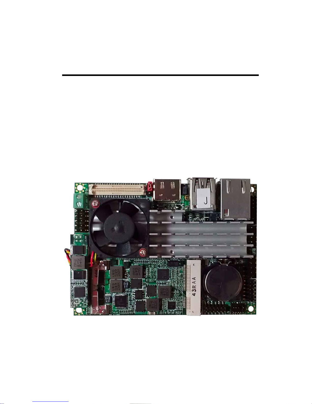
LP-173 Pico-ITX Miniboard x 1
Cable Kit:
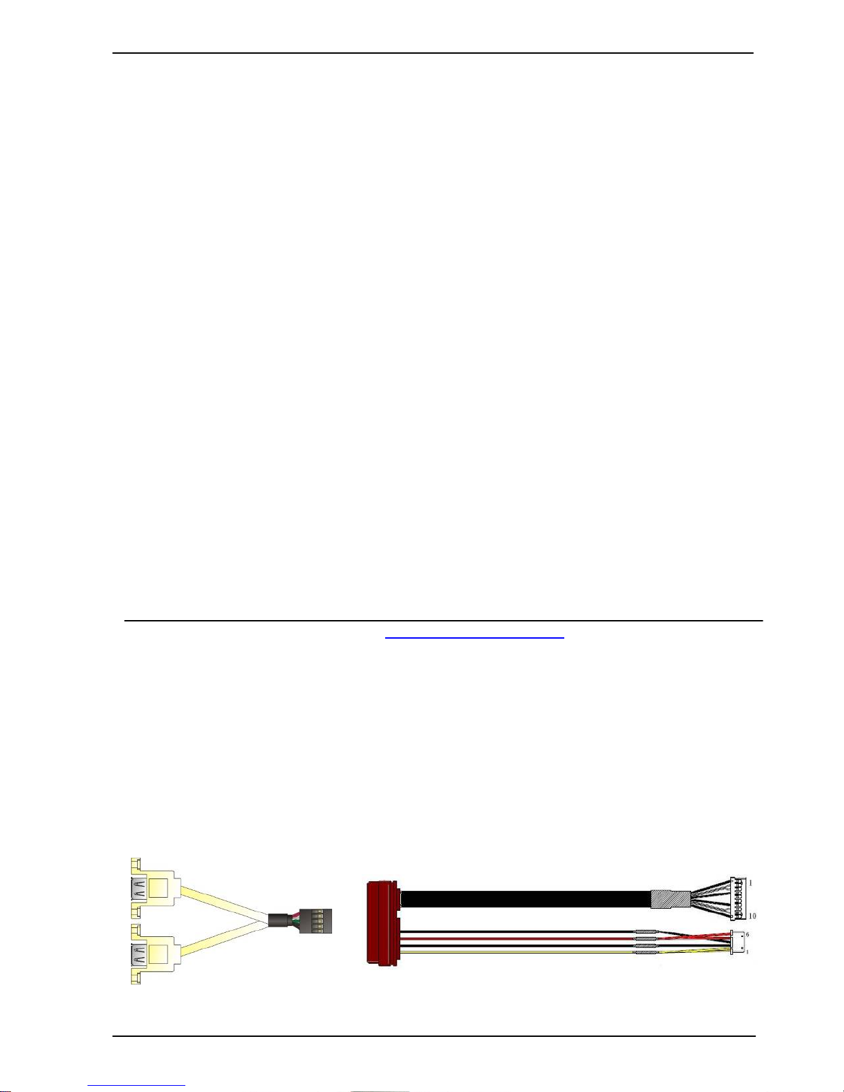
USB Cable x 1
(OALUSBA-3) / (1040173) SATA Cable x 1
(OALSATA22B-PM15SH15) / (1040512)
LP-173 User’s Manual
-3-
Index
Chapter 1 <Introduction>.................................................................................... 5
1.1 <Product Overview>..............................................................................................5
1.2 <Product Specification> ........................................................................................6
1.3 <Mechanical Drawing>.........................................................................................7
1.4 <Block Diagram> ..................................................................................................8
Chapter 2 <Hardware Setup>.............................................................................. 9
2.1 <Connector Location>...........................................................................................9
2.2 <Jumper Reference>............................................................................................10
Printed Matters:
Driver CD x 1 (Including User’s Manual)
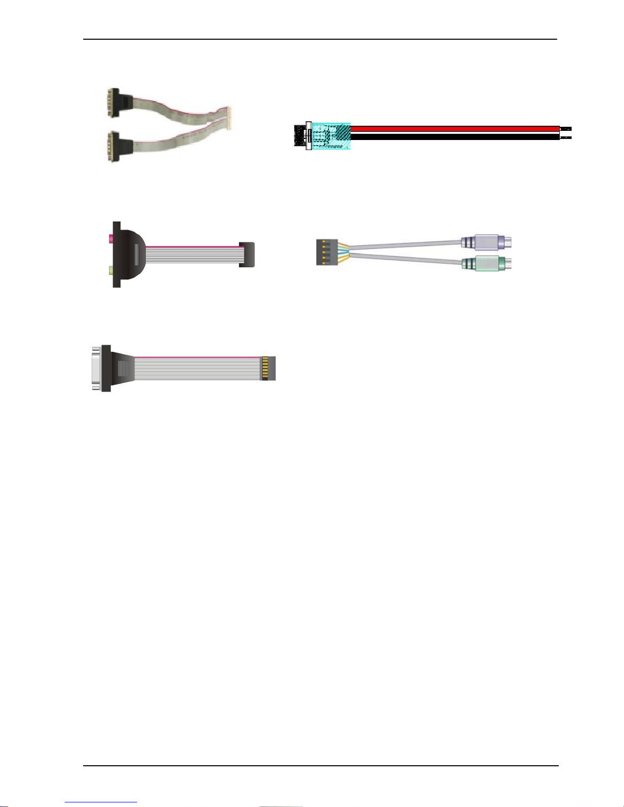
Audio Cable x 1
(OALPJ-HDUNB) / (1040123)
DC_IN Power Cable x 1
(OALDC-B) / (1040513)
PS/2 Keyboard & Mouse Cable x 1
(OALPS2/KM) / (1040131)
CRT cable without bracket x 1
(OALVGA-SNB-7) / (1040557)
RS232 Cable x 1
(OALES-BKU2-H14NB) / (1040379)

LP-173 User’s Manual
-4-
2.3 <Connector Reference>.......................................................................................10
2.3.1 <Internal Connector> ........................................................................10
2.3.2 <External Connector>.......................................................................10
2.4 <Memory Setup>.................................................................................................11
2.5 <CMOS & ATX Setup>......................................................................................11
2.6 <SATA Interface>...............................................................................................12
2.7 <LAN Interface> .................................................................................................12
2.8 <Onboard Display Interface> ..............................................................................12
2.8.1 <Analog VGA Interface>..................................................................12
2.8.2 <CN_LVDS>.....................................................................................13
2.9 <Onboard Audio Interface>.................................................................................16
2.10 <USB 3.0 and USB 2.0Interface> .....................................................................17
2.11 <Serial Port Jumper Setting >............................................................................19
2.12 <Power & FAN Connector >.............................................................................20
2.12.1 <Power Input>.................................................................................20
2.12.2 <Power Output>..............................................................................21
2.12.3 <Fan Connector>.............................................................................21
2.13 <Indicator and Switch>......................................................................................22
2.14 < PCIE Mini Card >...........................................................................................23
Chapter 3 <BIOS Setup>................................................................................... 24
Appendix A <I/O Port Pin Assignment> .......................................................... 25
A.1 <SATA Port>......................................................................................................25
A.2 <LAN Port>........................................................................................................25
A.3 <LPC Port>.........................................................................................................26
A.4 <GPIO Port>.......................................................................................................26
Appendix B <Flash BIOS> ................................................................................ 27
B.1 BIOS Auto Flash Tool.........................................................................................27
B.2 Flash Method.......................................................................................................27
Appendix C <Programming GPIO’s> ............................................................... 28

LP-173 User’s Manual
-5-
Appendix D <Programming Watchdog Timer >.............................................. 29
Contact Information........................................................................................... 31
Chapter 1 <Introduction>
1.1 <Product Overview>
The LP-173 motherboard is design based on Intel® Celeron® Processor J1900 / N2930
and Intel® Atom Processor E3845, delivering outstanding compute, graphical, and
media performance while operating in an extended range of thermal conditions. The
SoC bases on the Silvermont microarchitecture, utilizing Intel’s industry-leading 22nm
process technology with 3-D Tri-Gate transistors, which deliver significant improvements
in computational performance and energy efficiency.
New features for Intel® Celeron® and Atom Processor
The Intel® Celeron® Processor J1900 / N2930 and Intel® Atom E3845 Processor
supports graphics, media performance, flexibility and more enhanced security that is
suitable for a variety of intelligent systems the ideal choice.
Outstanding integration of I/O interfaces
Supports display interfaces with graphics processing, camera interfaces with image
processing, audio with digital signal processing, multiple storage types, and legacy
embedded I/O. Provides interface expansion capabilities through industry-standard
high-bandwidth interfaces such as PCI Express* Gen 2.0, Hi-speed USB 2.0, and USB
3.0 connectivity.
All in One multimedia solution
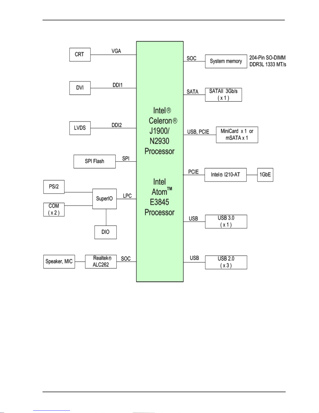
Based on Intel® J1900 / N2920 /E3845 SoC, the board provides high performance
onboard graphics, CRT, 24-bit dual channel LVDS interface, DVI and 2 channels High
Definition Audio, to meet the very requirement of the multimedia application.
LP-173 User’s Manual
-6-
Flexible Extension Interface
The board provides one PCIe mini slot
1.2 <Product Specification>
General Specification
Form Factor PICO-ITX miniboard
CPU Intel® Processor J1900/N2930/E3845, package type
FCBGA1170
Memory 1 x DDR3L (support 1.35V) 1066/1333 SO-DIMM up to 8GB
Watchdog Timer System reset programmable watchdog timer with 1 ~ 255
sec./min. of timeout value
Real Time Clock Chipset integrated RTC with onboard lithium battery
Serial ATA 1 x serial ATA interface with 300MB/s(3Gb/s) transfer rate
VGA Interface Intel® Clear Video integrated HD Graphics Technology
LVDS Interface 1 x Onboard 24-bit dual channel LVDS connector with +3.3V/+5V
supply
Audio Interface Realtek ALC262 High Definition Audio Codec
LAN Interface 1 x Intel® I210 Gigabit LAN
GPIO interface Onboard programmable 8-bit Digital I/O interface.
Extended Interface 1 x PCIE Mini card or mSATA
Internal I/O Port 2 x RS232, 1 x GPIO, 1 x Audio connector, 1 x CRT, 1 x LVDS, 1
x LPC, 2 x USB 2.0(EHCI) and 1 x SATAII
External I/O Port 1 x DVI port, 1 x RJ45 LAN port, 1 x USB 3.0(XHCI)/2.0(EHCI)
port,1 x USB 2.0(EHCI) port.
Power Requirement 6~27V DC Input
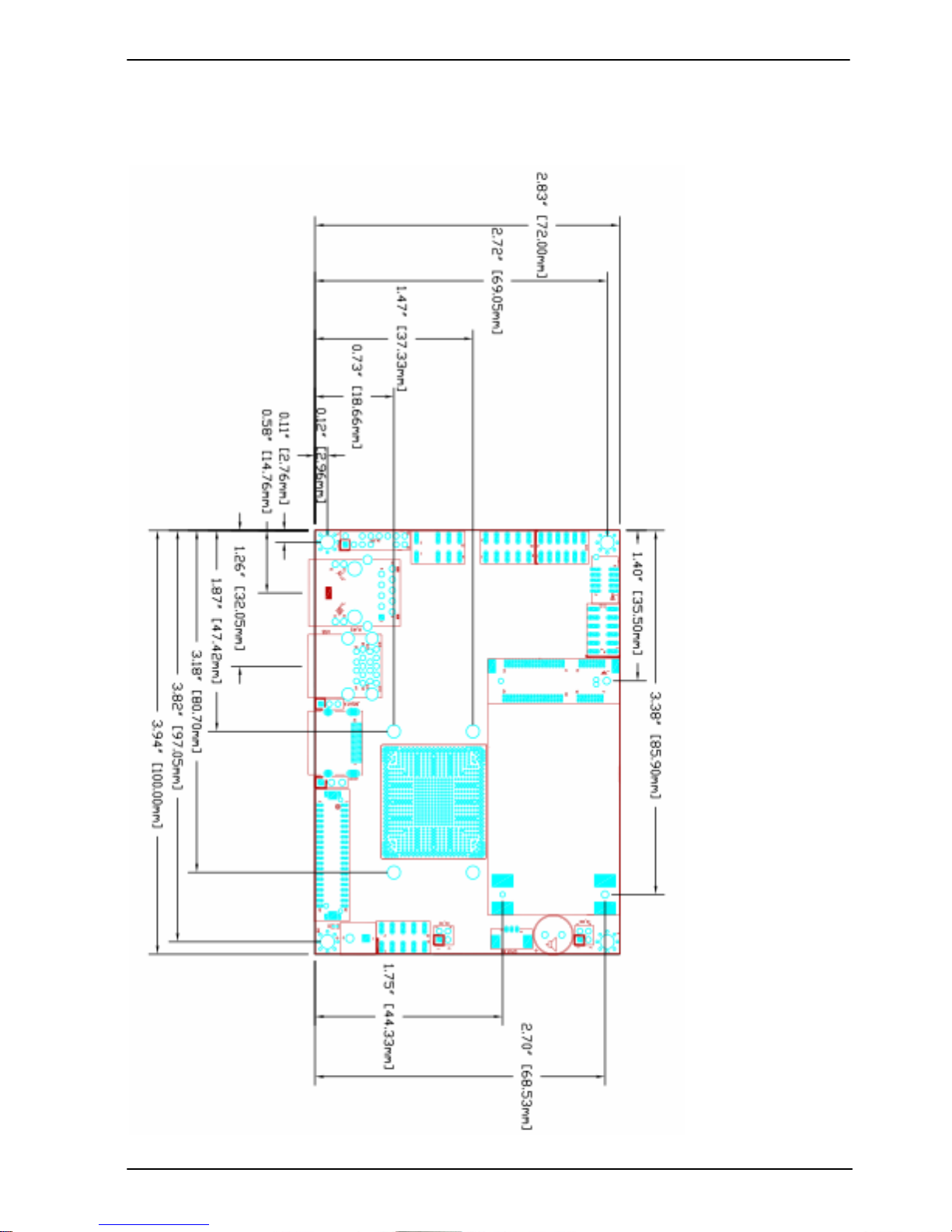
Dimension 100mm x 72mm
Temperature Operating within 0~60 ℃(for LP-173J and LP-173N serial)
Operating within -40~75 ℃(for LP-173E serial)
Ordering Code
LP-173J Intel Celeron Processor J1900 (2M Cache, 2.42GHz), DVI,
LVDS, CRT, Gigabit LAN, USB3.0 & 2.0, Serial Port, SATAII,
Audio, PCIE Mini card or mSATA, GPIO, LPC
LP-173N Intel Celeron Processor N2930 (2M Cache, 2.16GHz), DVI,
LVDS, CRT, Gigabit LAN, USB3.0 & 2.0, Serial Port, SATAII,
Audio, PCIE Mini card or mSATA, GPIO, LPC
LP-173E Intel Atom Processor E3845 (2M Cache, 1.91GHz), DVI, LVDS,
CRT, Gigabit LAN, USB3.0 & 2.0, Serial Port, SATAII, Audio,
PCIE Mini card or mSATA, GPIO, LPC
The specifications may be different as the actual production.
For further product information please visit the website at
TUhttp://www.commell.com.twUT
LP-173 User’s Manual
-7-
1.3 <Mechanical Drawing>
LP-173 User’s Manual
-8-
1.4 <Block Diagram>
LP-173 User’s Manual
-9-
Chapter 2 <Hardware Setup>
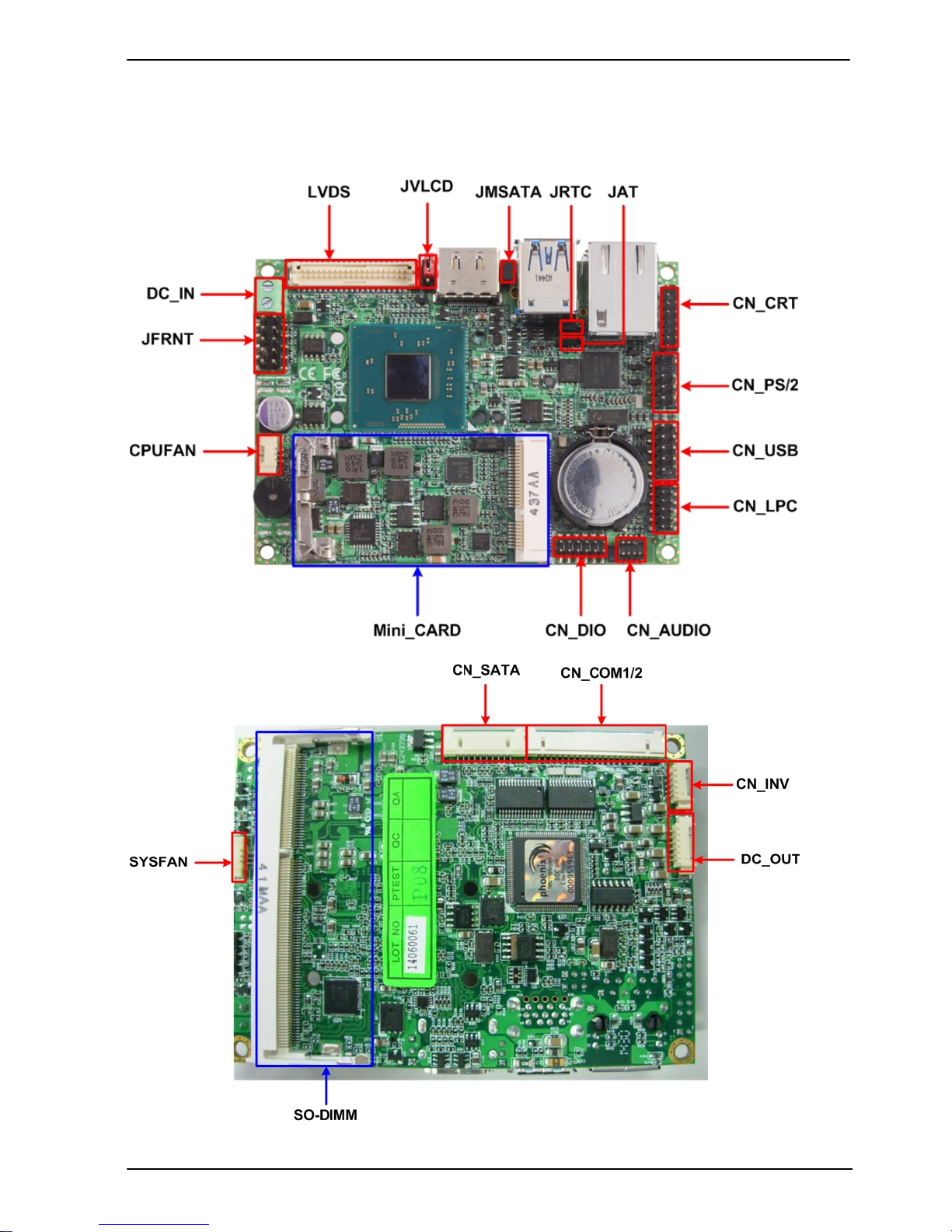
2.1 <Connector Location>
LP-173 User’s Manual
-10-
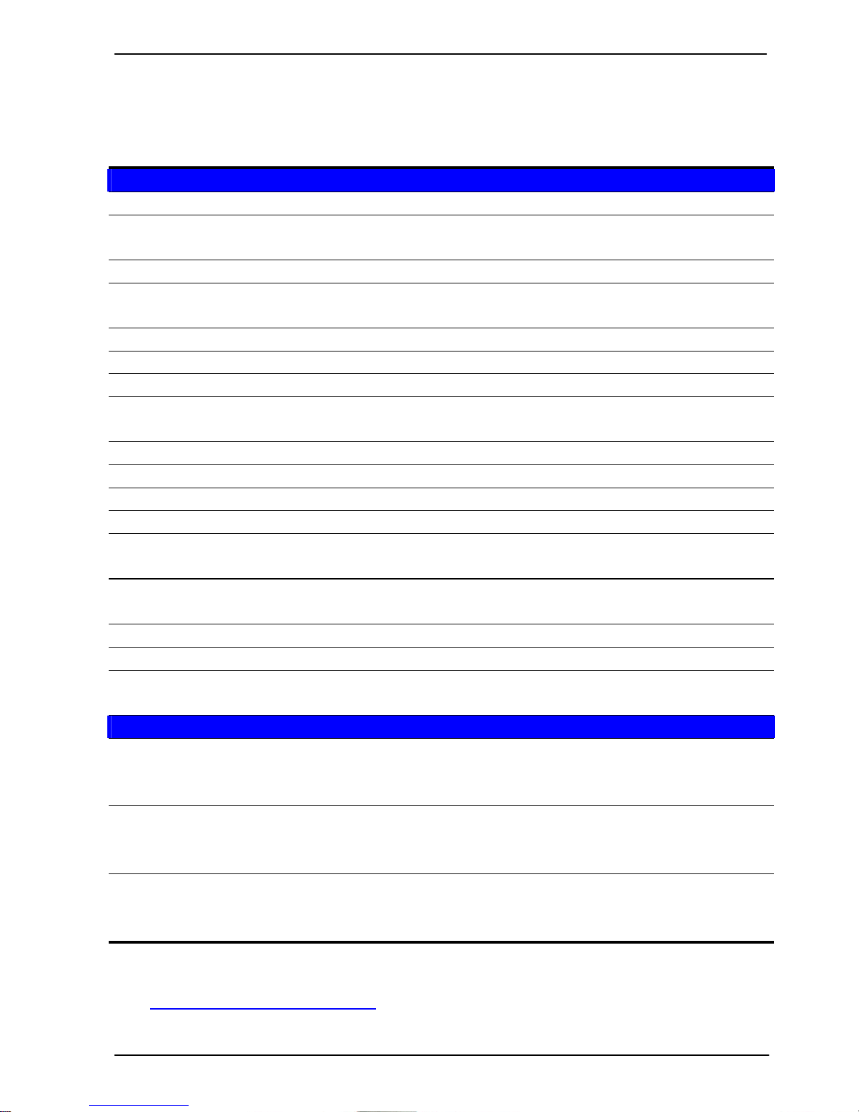
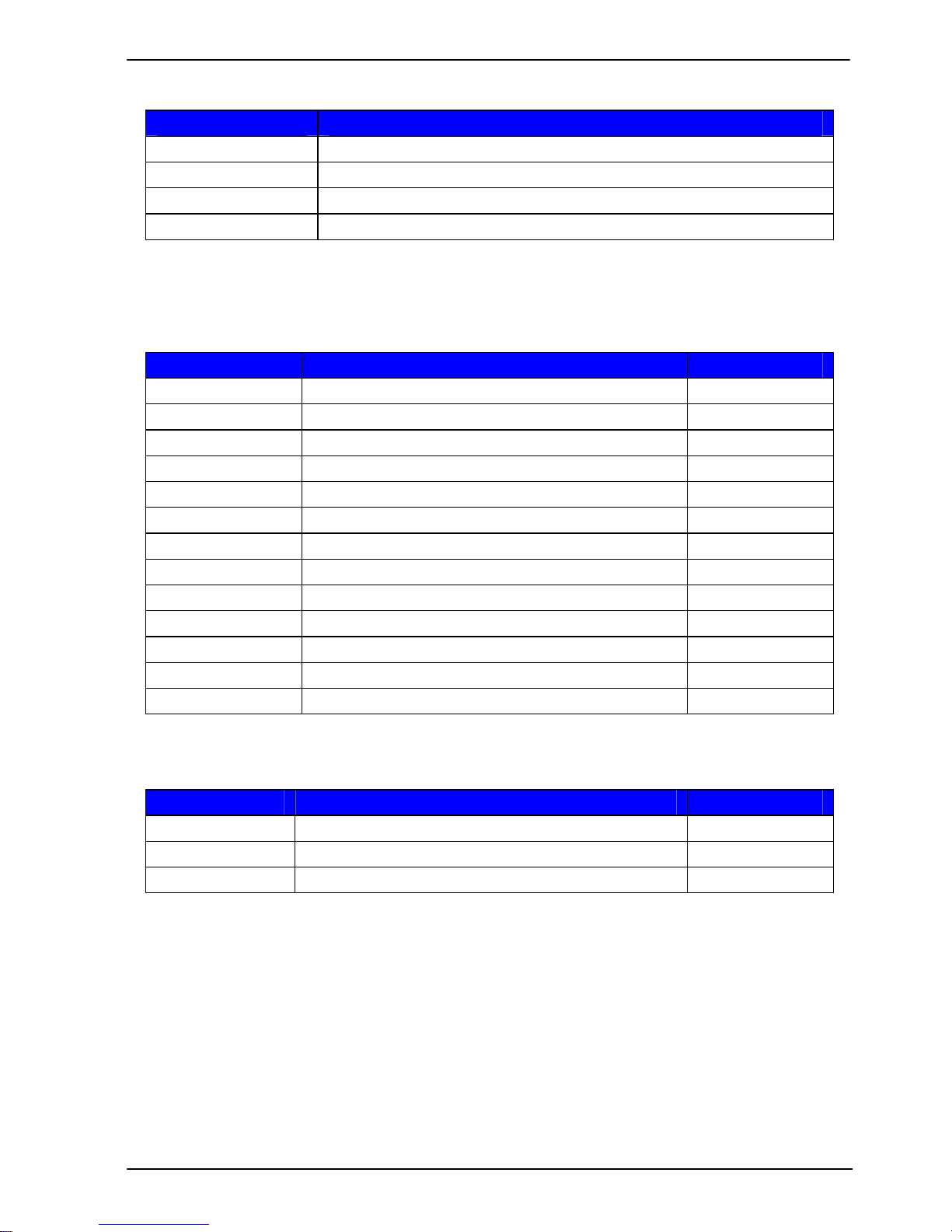
2.2 <Jumper Reference>
Jumper Function
JRTC CMOS Operating/Clear Setting
JAT AT/ATX Mode Setting
JVLCD LCD Panel Voltage Setting
JMSATA Mini Card1 mSATA Setting
2.3 <Connector Reference>
2.3.1 <Internal Connector>
Connector Function Remark
SO-DIMM 204 -pin DDR3L SO-DIMM SDRAM slot
CN_SATA 10-pin SATA Cable connector
MINI_CARD PCIE mini card socket
CN_INV 5-pin LCD inverter connector
CN_USB1/2 5 x 2-pin USB connector
CN_AUDIO 5 x 2-pin audio connector
CN_LPC 5 x 2-pin header for LPC Port
CN_COM1/2 10 x 2-pin com connector
JFRNT 10-pin switch/indicator connector
CPUFAN 3-pin CPU cooler fan connector
SYSFAN 3-pin system cooler fan connector
DC_OUT 6-pin power output connector
DC_IN DC input connector
2.3.2 <External Connector>
Connector Function Remark
DVI 19-pin HDMI connector
USB 1/2 USB 2.0 and USB 3.0 connector
RJ45 RJ45 LAN connector
Other manuals for LP-173
1
Table of contents
Other Commell Motherboard manuals

Commell
Commell LS-573 User manual

Commell
Commell LV-66A User manual

Commell
Commell P4LA User manual

Commell
Commell LV-667 User manual

Commell
Commell LN-D70 User manual

Commell
Commell PMCA User manual

Commell
Commell LE-370 User manual

Commell
Commell LV-672 User manual

Commell
Commell LE-37N7 User manual

Commell
Commell FS-977PRO User manual

Commell
Commell LS-372 User manual

Commell
Commell LS-371E User manual

Commell
Commell LV670 Series User manual

Commell
Commell LS-371 User manual

Commell
Commell LV-67F User manual

Commell
Commell EE-260 User manual

Commell
Commell ADP-TPM User manual

Commell
Commell LV-67H-G User manual

Commell
Commell LV-666 User manual

Commell
Commell LV-681 User manual


