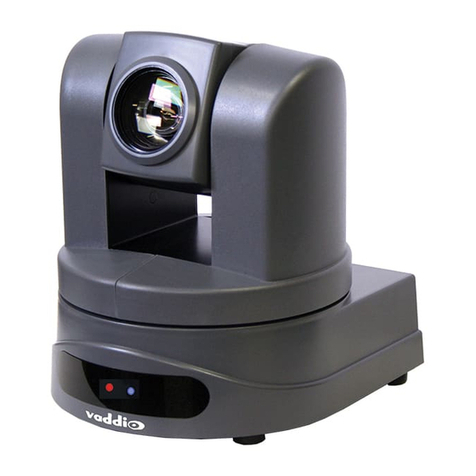
CNB IPM3063N User manual

INSTRUCTION MANUAL Ver 1.0
Interior Network Speed Dome Camera / IPM 06 N(P)
( 810-0204A)

This lightning flash with arrowhead symbol is intended to alert the
user to the presence of un-insulated "dangerous voltage" within the
product's enclosure that may be of sufficient magnitude to constitute
a risk of electric shock to persons.
This exclamation point symbol is intended to alert the user to the
presence of important operating and maintenance (servicing)
instructions in the literature accompanying the appliance.
WARNING TO PREVENT THE RISK OF FIRE OR ELECTRIC SHOCK HAZARD,
DO NOT EXPOSE THIS CAMERA TO RAIN OR MOISTURE.
◎Read all of the safety and operating instructions before using the product.
◎Save these instructions for future reference.
◎Do not use attachments or accessories unless recommended by the appliance
manufacturer as they may cause hazards, damage product and void warranty.
◎Do not use this product near water or moisture.
◎Do not place or mount this product in or on an unstable or improperly supported location.
Improperly installed product may fall, causing serious injury to a child or adult, and
damage to the product. Use only with a mounting device recommended by the
manufacturer, or sold with the product. To insure proper mounting, follow the
manufacturer's instructions and use only mounting accessories recommended by
manufacturer.
◎This product should be operated only from the type of power source indicated on the
marking label.
◎Before using, make sure power supply and others are properly connected.
◎While operating, if any abnormal condition or malfunction is observed, stop using the
camera immediately and then contact your local dealer.
◎Do not disassemble or tamper with parts inside the camera.
◎Do not drop or subject the camera to shock and vibration as this can damage camera.
◎Care must be taken when you clean the clear dome cover. Especially, scratch and dust
will ruin your quality of camera.
◎Do not install the camera in areas of extreme temperature, which exceed the allowable
range.
◎Avoid installing in humid or dusty places.
◎Avoid installing in places where radiation is present.
◎Avoid installing in places where there are strong magnetic fields and electric signals.
◎Avoid installing in places where the camera would be subject to strong vibrations.
◎Never expose the camera to rain and water.
◎Don’t connect the RJ-45 cable to a terminal by constraint.
CAUTION : TO REDUCE THE RISK OF ELECTRICAL SHOCK, DO NOT OPEN COVERS.
NO USER SERVICEABLE PARTS INSIDE.
REFER SERVICEING TO QUALIFIED SERVICE PERSONAL.
CAUTION
RISK OF ELECTRIC
SHOCK DO NOT OPEN
Important Safeguard
Precautions
Warnings Cautions

Features
Product
Installation
Web Viewer
Camera Operation
48Configuring Event Type ----------------------------------------------------------------------------
50SMTP Setup -------------------------------------------------------------------------------------------
52Configuring FTP --------------------------------------------------------------------------------------
53Configuring and operating PTZ ------------------------------------------------------------------
55Configuring Motion Detection area --------------------------------------------------------------
35Generating Log Report -----------------------------------------------------------------------------
36Configuring Audio ------------------------------------------------------------------------------------
37Configuring Video ------------------------------------------------------------------------------------
39Configuring RTP/RTSP -----------------------------------------------------------------------------
40Configuring the Network (TCP/IP) parameters -----------------------------------------------
42Configuring IP Filtering -----------------------------------------------------------------------------
44Configuring HTTP ------------------------------------------------------------------------------------
45Configuring UPnP/DynDNS/Bonjour ------------------------------------------------------------
47Configuring CMS -------------------------------------------------------------------------------------
21Page Access Authority ------------------------------------------------------------------------------
System Administration ----------------------------------------------------------------------------- 18
Configuring Speed Dome ------------------------------------------------------------------------- 20
Web Viewer ------------------------------------------------------------------------------------------- 22
Status Window --------------------------------------------------------------------------------------- 24
Configuring Users ------------------------------------------------------------------------------------ 25
Setting Date & Time --------------------------------------------------------------------------------- 27
Configuring Multi-Viewer --------------------------------------------------------------------------- 29
Configuring PTZ -------------------------------------------------------------------------------------- 29
Maintain Server Configurations ------------------------------------------------------------------ 33
Configuring Multi View Option -------------------------------------------------------------------- 57
------------------------------------------------- 6
63OSD Display of Main Screen -----------------------------------------------------------------
62Others Functions --------------------------------------------------------------------------------
59Starting OSD Menu -----------------------------------------------------------------------------
59PRESET -------------------------------------------------------------------------------------------
60SWING ---------------------------------------------------------------------------------------------
60PATTERN -----------------------------------------------------------------------------------------
61GROUP --------------------------------------------------------------------------------------------
65Compass Direction Setup ---------------------------------------------------------------------
General Rules of Key Operation for Menu ----------------------------------------------- 64
MAIN MENU ------------------------------------------------------------------------------------- 64
DISPLAY SETUP ------------------------------------------------------------------------------- 64
PRIVACY ZONE MASK SETUP ----------------------------------------------------------- 65
CAMERA SETUP ------------------------------------------------------------------------------- 66
MOTION SETUP ------------------------------------------------------------------------------- 68
PRESET SETUP ------------------------------------------------------------------------------- 70
SWING SETUP --------------------------------------------------------------------------------- 72
PATTERN SETUP ----------------------------------------------------------------------------- 72
GROUP SETUP -------------------------------------------------------------------------------- 73
SYSTEM INITIALIZE -------------------------------------------------------------------------- 76
------------------------------------------------- 8
------------------------------------------------- 9
Specifications ---------------------------------- 78

◎CCD Sensor 1/4” Interline Transfer CCD
◎10x Optical Zoom, 10x Digital Zoom (Max. 100x Zoom)
◎Day & Night Function
◎Various Focus Mode Auto-Focus / Manual Focus / Semi-Auto Focus.
◎Independent & Simultaneous Camera Characteristic Setup in Preset operation
◎Support D1, CIF output resolution.
◎MJPEG, MPEG4, H.264 codec selectable.
◎Max. 30 frame/sec support.
◎Support Dual Stream.
◎Bi-direction audio support (ADPCM, G.726)
◎Up to 10 users can be connected.
◎Support protocols IPv4, HTTP, TCP, RTSP, UDP, SMTP, FTP, ICMP, DHCP, UPnP,
Bonjour, ARP, DNS, DynDNS.
◎Support Motion Detection (Up to 3 motion detection area can be defined).
◎When event occurred, image save function (JPEG file, Internal memory, SD Card).
◎Max. 360°/sec high speed Pan/Tilt Movement.
◎Using Vector Drive Technology, Pan/Tilt motions are accomplished in a shortest path.
As a result, time to target view is reduced dramatically and the video on the monitor is
very natural to watch.
◎For jog operation using screen jog, since ultra slow speed 0.05°/sec can be reached,
it is very easy to locate camera to desired target view. Additionally it is easy to move
camera to a desired position with zoom-proportional pan/tilt movement.
◎Max. 127 Presets are assignable and characteristics of each preset can be set up
independently, such as White Balance, Auto Exposure, Label and so on.
◎Max. 8 set of Swing action can be stored. This enables to move camera repetitively
between two preset positions with designated speed.
◎Max. 4 of Patterns can be recorded and played back.
◎Max. 8 set of Group action can be stored. This enables to move camera repetitively
with combination of Preset or Pattern or Swing. A Group is composed of max. 20
entities of Preset/Pattern/Swings.
◎Privacy Masks are assignable, not to intrude on other’s privacy. (4 Privacy Zones)
◎OSD menu is provided to display the status of camera and to configure the functions
interactively.
◎The information such as Camera ID, Pan/Tilt Angle, Iris, Alarm Input and Preset can
be displayed on screen.
◎4 alarm sensor Inputs and 1 alarm output relay are available.
◎To reject external electric noise and shock perfectly, alarm sensor Input is decoupled
with photo coupler.
◎To reject external electric noise and shock perfectly, alarm sensor Input is decoupled
with photo coupler.
◎The signal range of sensor input is from DC 5.0 to 12.0 volts to adopt various
applications.
◎Relay output is able to connect. (max. 125V AC/0.5A or 24V DC/1A)
◎If an external sensor is activated, camera can be set to move to the corresponding
Preset position.
Camera Specifications
Network Specifications
Alarm In/Out Functions
Preset, Pattern, Swing, Group, Privacy Mask ..
OSD(On Screen Display) Menu
7
6
Powerful Pan/Tilt Functions

①Install Ceiling Bracket on Ceiling.
②Attach the product installation bracket to the camera.
③Line up the mold lines and assemble main body to ceiling bracket. Turn main body
on its axis in CW (Clockwise) direction and after assembling then.
Basic Components
Main Body
Video Connect
Ceiling Bracket Product Bracket
Cable Cover Guide Pattern Manual
DC Adaptor Screws
9
8
Install CD
IPM 06 N(P) Installation

④Fix the camera with the fixing screw.
⑤Insert the Cable Cover into Ceiling Bracket. and fix it with the supplied fixing screw.
◎Power Connection
- The standard power for the system is 12V DC/1A
Please, check the voltage and current capacity of rated power carefully.
Rated power is included in the back of main unit.
◎Video Connection
- Connect with the supplied Cable. (For installation)
◎AUDIO IN/OUT
- Connect with audio input/output device.
IPM 06 N(P) Installation
11
10
Cabling
RATED POWER INPUT VOLTAGE RANGE CURRENT CONSUMPTION
12V DC 11V ~ 18V DC 1A
Relay Output
Image Output Device (for installation)
POWER
IrDA Sensor
Door Switch
Ethernet/LAN

ㆍSelect Internet Protocol (TCP/IP) and click the “Properties” button below,
then press “Advanced…” to set advanced options for your PC.
ㆍ192.168.123.XXX as the internal IP of your computer. 192.168.12 .100 is the
IP address for the camera and will be unavailable as the internal IP address for
your computer.
◎LAN Connection
- Single Connection
Notes.
ㆍIf single network connection, you must register the internal IP of your computer.
To register the IP, go to My Network Environment -> Properties -> Local Area
Connection -> Properties.
Cabling
1
12
LAN
Web Viewer / CMS
XXX

◎LAN Connection
- Multiple Connection
.
◎SD CARD
- When the alarm input and Motion detection occurred, image save memory.
- SC Card is not provided in this product’s package. (512K~4G Bytes)
◎UPGRADE
- Speed Dome Firmware Upgrade (Using Update Stick)
- This function is not supported now.
◎Before connecting sensors, check driving voltage and output signal type of the sensor.
Since output signal types of the sensors are divided into Open Collector and Voltage
Output type in general, the cabling must be done properly after considering these
typed.
◎If you want to use Alarm Input, the types of sensor must be selected in OSD menu.
The sensor types are Normal Open and Normal. If sensor type is not selected properly,
the alarm can be activated reversely.
Sensor InputCabling
15
14
Signal Description
COM+ Connect (+) cable of electric power sources for Sensors to this port
as shown in the circuit above.
IN1-, IN2-,
IN - , IN4-
Connect output of sensors for each port as shown in the circuit
above.
DescriptionType
Normal Open Output Voltage is high state when sensor is activated
Normal Close Output Voltage is high state when sensor is not activated
Internal Circuit
+ -
+-
IN 1-
IN 4-
Sensor Output 1
Sensor Output 4
IN COM+
+5V ~ 12V
LAN
#1 #2 #n
ROUTER INTERNET
LAN LAN
Web Viewer / CMS

◎Maximum allowable electrical load of relay is shown bellow table.
17
16
Web Viewer
Relay Output
Driving Power DC 110V AC
Max. Load 24V DC, 1A 125V AC, 0.5A
LOAD
AC or DC
Internal Circuit
OUT 1

◎The default user name and password is “root” and “admin” respectively.
For security purpose, it is recommended to change the administrator’s id and password
from their default values. Please be careful not to forget them or expose them to
others. Please refer to “User Setting” for detail
If you forget the administrator’s password, “Factory Reset” is the only way to regain
access. However, since this will retrieve all default settings, you need to configure the
network settings using IP installer software again.
◎Logging On
ㆍYou can log on as an administrator using either Internet browser or ‘CMS’
software. (This manual will describe about using Internet browser only.)
◎Using IP Installer
ㆍIf IP Installer execute, IP camera’s information is displayed.
◎Using Internet Explorer
ㆍType the IP Address of the XPEED-XNET product in the address bar and press enter.
Ex) http //192.168.123.100
If the HTTP Port has been changed from the default value, enter the new port as
shown below.
IP Address of the XPEED-XNET Port No.
Ex) http //192,168.123.100 8080
◎ID and Password
ㆍIf you are logging in as an administrator, the Log-In box will appear as shown
in following figure. Basic Setup page will appear when you enter id and password.
System Administration
19
18
This manual suits for next models
1
Table of contents
Languages:
Other CNB Security Camera manuals

CNB
CNB XNET IGP2035F User manual

CNB
CNB XNET IGP1030 User manual

CNB
CNB IDC4050IR User manual

CNB
CNB DBM20S User manual

CNB
CNB XPEED SDN-22Z27F User manual

CNB
CNB XNET IVC5055VR User manual

CNB
CNB XNET IVC5055VR User manual

CNB
CNB IDP4030VR Operating instructions

CNB
CNB LKC1050IR User manual

CNB
CNB XNET IVC5055VR User manual