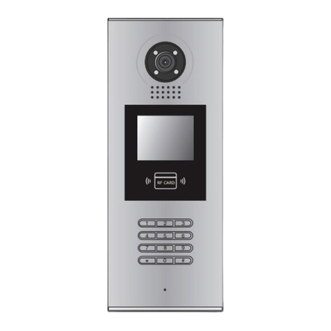
CDVI CDV97-1ID User manual

USER MANUAL
RF CARD RF CARD
RF CARDRF CARD
2 WIRE SYSTEM
Fisheye door station with proximity access control
CDV97-V1 / 201609
CDV97 Series
CDV97-4IDCDV97-1ID CDV97-2ID
CDV17-97A
Please read carefully to ensure safe and correct operation
Keep this manual safe for future use

CONTENTS
PARTS AND FUNCTIONS..................................................................................... 3
Part Names............................................................................................................. 3
Mounting................................................................................................................. 4
BASIC FUNCTIONS .............................................................................................. 6
Unlock Operations.................................................................................................. 6
Fisheye Camera ..................................................................................................... 6
External Motion Detection ...................................................................................... 6
SETUP INSTRUCTIONS........................................................................................ 7
Functions Setting Up .............................................................................................. 7
Setting Door Station Address ................................................................................. 8
Setting Door Station Calling Mode ......................................................................... 8
Setting Camera Resolution.................................................................................... 10
Setting Unlock Mode ............................................................................................. 10
Setting Unlock Time............................................................................................... 11
Setting Nameplate Illumination Mode.................................................................... 11
Setting Night View LED Illumination Mode............................................................ 12
Setting Ring-back Tone ......................................................................................... 12
Setting Image Display Mode.................................................................................. 13
Registering ID Card............................................................................................... 14
WIRING ................................................................................................................. 17
Connecting Electric Lock....................................................................................... 17
Connecting Basic One-to-one ............................................................................... 18
Connecting Multi Door Stations............................................................................. 18
Connecting Multi Monitors..................................................................................... 19
APPENDIX ............................................................................................................ 21
Precautions............................................................................................................ 21
Specication .......................................................................................................... 21
Cables and Requirements..................................................................................... 22

-3-
Part Names
PARTS AND FUNCTIONS
[11]
[10]
[14]
[9]
[1]
[3]
[4]
[1]
[3]
[4]
[8]
[7]
[6]
[5]
[9]
[8]
[7]
[6]
[5]
[12]
[11]
[12]
[13]
[13]
[2]
[2]
Surface mounted
Flush mounted
[1] Microphone
[2] UNLOCK indicator
[3] CALL indicator
[4] Call button
[5] Nameplate
[6] Front panel
[7] Speaker
[8] Night view LED
[9] Camera lens
[10] Rain Shield
[11] Mounting hook
[12] Connection port
[13] Screw hole
[14] Mounting box

-4-
PARTS AND FUNCTIONS
Mounting
1 2 3 4 5
AcDbMLeader (ACDB_MLEADER_CLASS)
AcDbMLeader (ACDB_MLEADER_CLASS)
Rainy cover
Rainy cover
The distance between
the top of main unit
and rain cover should
be not less than 3mm.
Main unit
Main unit
≥3mm
1 2 3 4 5
AcDbMLeader (ACDB_MLEADER_CLASS)
AcDbMLeader (ACDB_MLEADER_CLASS)
AcDbMLeader (ACDB_MLEADER_CLASS)
1. Connect the cable correctly.
Surface mounted
Flush mounted
* The camera angle view of surface mount model may be less than 1700.
The installation height is suggested at 145~160cm.
3. Install the name plate.
4. Attach the front panel to the main unit.
5. Use the special screwdriver and the screws to x the panel.
1. Drill a hole in the wall to match the size of mounting box, then attach the mounting box to the
wall.
2. Loosen the high screws to install the name plate.
3. Connect the cable correctly.
4. Attach the front panel to the mounting box, then use the special screwdriver and the screws to
x the panel.
5. Finish the installation.
2. Drill holes in the wall to match the size of screw wall plugs,then attach the rain shield
and main unit to the wall, the distance between the top of main unit and rain cover should not be
less than 3mm.

-5-
PARTS AND FUNCTIONS
Terminal description
Lock Control Jumper: To select the lock type.
Motion Detector Connect Port: To connect external PIR motion detector.
Main Connect Port: To connect the bus line and the electronic locks.
• L1,L2: Connect to the bus line, no polarity.
• PL: External lock power input, connect to the power positive(power +).
• S+: Lock power(+) output.
• S-: Lock power(-) output, connect to the power(-) input of locks(only when using the door
station to power the locks, if using the external power supply for the locks, the S- will not be
connected).
1 2 3
Lock Control Jumper
PIR Motion Detector
Connect Port
+12V
GND
PIR
L1 L2
PL
S+ S-
Main Connect Port

-6-
BASIC FUNCTIONS
Unlock Operations
Fisheye Camera
External Motion Detection
Standard
door station angle
DT607
1700door camera angle
(Wide angle view shown)
12V
GND
PIR
Unlocking by ID Card/Tag
When the registered user card is shown to the ID card window, the UNLOCK indicator lights up,
the buzzer sounds,and the electric door strike is unlocked.
• Present an unauthorized user card, the buzzer will beep three times
• Present an authorised user card, the buzzer will beep once, the UNLOCK indicator will
light up and the connected lock will release.
Please note that this function requires a
monitor with sheye function support.
The angle view is 1700,visitors within this
angle of view can be seen clearly zoom can
also be used to view individuals in close up
via the indoor monitor with sheye function.
If the external motion detector is connected
to the system the following functions will be
effective:
'When detecting someone passing by, the door
station can be set to unlockor turn on a light.
* Please contact your supplier for more details regarding detector connection.
The door station is equipped with terminalsto
enable connection of an external motion
detector*.
Motion
detector*

-7-
SETUP INSTRUCTIONS
Functions Setting Up
KEY_1
KEY_2
KEY_3
KEY_4
KEY_SET
LED_UNLOCK
LED_TALK
LED_NAME
RF CARD
Order Setting items Setting range Default value
1 Setting door station address 0~3 0
2Setting door station
calling mode Standard/Group calling mode Standard calling mode
3 Setting camera resolution High/Low High
4 Setting the unlock mode 0:opened/1:closed 0:opened
5 Setting the unlock time 01 to 99 seconds 1 seconds
6Setting the nameplate
illumination mode On/Off/Auto On
7Setting night view LED
illumination mode On/Off/Auto Auto
8 Setting ring-back tone
Ringing one time
Ring continuously
No ring-back tone
Ringing one time
9 Setting image display mode
Alternate switching mode
Zoom mode
Full screen mode
Alternate switching mode
This section explains the settings of each
function. Please refer to the following table:
Each operation is indicated by the lighting
of the LED indicator on the unit and by the
sounding of the buzzer.
To perform the settings for the function
required,remove the metal front panel to
gain access to the 'Key Set' button.
Please refer to the diagram (right).

-8-
Setting Door Station Address
Setting Door Station Calling Mode
UNLOCK Indicator:OFF
TALK Indicator:OFF Buzzer Beep+, Beep
UNLOCK Indicator:OFF
TALK Indicator:OFF
Buzzer Beep+
In standby mode, press
KEY_SET button once
Press KEY_1 button to set
the first door station.
Press KEY_2 button to set
the second door station.
Press KEY_3 button to set
the third door station.
Press KEY_4 button to set
the fourth door station.
UNLOCK Indicator:OFF
TALK Indicator:OFF
Buzzer Beep,Beep
UNLOCK Indicator:OFF
TALK Indicator:OFF
Buzzer Beep,Beep,Beep
UNLOCK Indicator:OFF
TALK Indicator:OFF
Buzzer Beep,Beep,Beep,Beep
SETUP INSTRUCTIONS
A total of 4 addresses can be congured. They can be modied either before or after
installation. 0 is default, to change the setting, please use the following steps:
ID=0,1st door station ID=1,2nd door station ID=2,3rd door station ID=3,4th door station
• While in the setting mode, the address of door station can be changed by pressing KEY1~4 freely.
• The LED_NAME indicator will continually flash while in the setting mode.
• If no operation is carried out within 10 s the setting mode will exit automatically.
• To exit the setting mode manually press the KEY_SET button four times.
There are two calling modes for door station, Standard calling mode and Group calling
mode. Please note that the door station operates in Standard calling mode by default.

-9-
SETUP INSTRUCTIONS
UNLOCK Indicator:OFF
TALK Indicator:ON
Buzzer Beep+, Beep
UNLOCK Indicator:OFF
TALK Indicator:ON
Buzzer Beep+
Press KEY_1 button to
activate Standard calling
mode for door station.
UNLOCK Indicator:OFF
TALK Indicator:ON
Buzzer Beep, Beep
Press KEY_1 button again
to activate Group calling
mode for door station.
Press KEY_1
A
B
C
D
A A
B
RF CARDRF CARD
Call button A: callsmonitor address 01 by default.
Call button B: calls monitor address 02 by default.
Call button C: callsmonitor address 03 by default.
Call button D: callsmonitor address 04 by default.
2. Group calling mode
1. Standard calling mode(Address range 01-04
by default)
Call button A: Callsall the monitors in the group
address 00~15.(One monitor must be set to 00)
Call buttons B,C,D: Callsall the monitors in the group
address 16~31.(One monitor must be set to 16)
* For more details regarding code settingsfor the monitor, please refer to corresponding user manual .
To change the call setting, please follow the steps:
In standby mode, press
KEY_SET button twice.
• If no operation is carried out within 10 s the setting mode will exit automatically.
• To exit the setting mode manually press the KEY_SET button four times.
• The LED_NAME indicator will continually flash while in the setting mode.
• While in the setting mode, the calling code can be changedmode by pressing KEY1 cyclically.
Each call button will respond different addresses when set in different calling mode. Refer to the
following for more information.

-10-
Setting Camera Resolution
Setting Unlock Mode
High resolution is default, to change the setting, please follow the steps:
UNLOCK Indicator:OFF
TALK Indicator:ON
Buzzer Beep+, Beep
In standby mode, press
KEY_SET button twice.
UNLOCK Indicator:OFF
TALK Indicator:ON
Buzzer Beep+
Press KEY_2 button to set the
camera to High resolution.
UNLOCK Indicator:OFF
TALK Indicator:ON
Buzzer Beep, Beep
Press KEY_2 button again
to set the camera to Low
resolution.
Press KEY_2
UNLOCK Indicator:ON
TALK Indicator:OFF
Buzzer Beep+, Beep
In standby mode, press
KEY_SET button three
times.
UNLOCK Indicator:ON
TALK Indicator:OFF
Buzzer Beep+
Press KEY_1 button to set
the unlock mode to
Normally opened.
UNLOCK Indicator:ON
TALK Indicator:OFF
Buzzer Beep, Beep
Press KEY_1 button again
to set the unlock mode to
Normally closed.
Press KEY_1
SETUP INSTRUCTIONS
The resolution of the camera can be changed between high and low quality at the door station.
• If no operation is carried out within 10 s the setting mode will exit automatically.
• To exit the setting mode manually press the KEY_SET button four times.
• While in the setting mode, the calling code can be changedmode by pressing KEY2cyclically.
• The LED_NAME indicator will continually flash while in the setting mode.
There are 2 unlock modes, Normally open and Normally closed.
Normally open is default, to change the setting, please follow the steps:
• If no operation is carried out within 10 s the setting mode will exit automatically.
• To exit the setting mode manually press the KEY_SET button four times.
• While in the setting mode, the lock mode can be changedmode by pressing KEY1 cyclically.•
The LED_NAME indicator will continually flash while in the setting mode.
This manual suits for next models
3
Table of contents
Other CDVI Intercom System manuals

CDVI
CDVI CDV-DDP-F User manual

CDVI
CDVI CDV-4791S-DXB User manual

CDVI
CDVI 2EASY CDV-T5 User manual

CDVI
CDVI 2EASY CDV-96KP User manual

CDVI
CDVI 2EASY CDV-47DX User manual

CDVI
CDVI CDV97-8ID Series User manual

CDVI
CDVI CDV-91 User manual

CDVI
CDVI CDV91S User manual

CDVI
CDVI CDV91F User manual

CDVI
CDVI KCIEN User manual

CDVI
CDVI CDV96KP User manual

CDVI
CDVI 2Easy CDV4796KP-DX User manual

CDVI
CDVI CDV4791 User manual

CDVI
CDVI CD97-4ID User manual

CDVI
CDVI 2EASY CDV-91S User manual

CDVI
CDVI DMR18S User manual

CDVI
CDVI CDV4796KP-DX User manual

CDVI
CDVI CDV4791S-DX User manual

CDVI
CDVI CDV-471IP User manual

CDVI
CDVI CDV96KP User manual