Biostar iDEQ-T1 IN294KT1 User guide

iDEQ-T1 IN294KT1 Setup Manual
FCC Information and Copyright
This equipment has been tested and found to comply with the limits of a Class B
digital device, pursuant to Part 15 of the FCC Rules. These limits are designed to
provide reasonable protection against harmful interference in a residential installation.
This equipment generates, uses, and can radiate radio frequency energy and, if not
installed and used in accordance with the instructions, may cause harmful
interference to radio communications. There is no guarantee that interference will not
occur in a particular installation.
The vendor makes no representations or warranties with respect to the contents here
and specially disclaims any implied warranties of merchantability or fitness for any
purpose. Further the vendor reserves the right to revise this publication and to make
changes to the contents here without obligation to notify any party beforehand.
Duplication of this publication, in part or in whole, is not allowed without first obtaining
the vendor’s approval in writing.
The content of this user’s manual is subject to be changed without notice and we will
not be responsible for any mistakes found in this user’s manual. All the brand and
product names are trademarks of their respective companies.

iDEQ-T1 IN294KT1 Setup Manual
Table of Contents
Chapter 1: Introduction..................................................................................... 1
Getting Started............................................................................................. 1
Package Checklist ....................................................................................... 1
Specification................................................................................................. 2
Getting to Know Your System ...................................................................... 3
Chapter 2: System hardware installation........................................................ 4
Disassembling the Cover............................................................................. 4
A. Installing WiFi Module ............................................................................. 5
C. Installing a 2.5 inch HDD......................................................................... 6
VESA Bracket (Optional).............................................................................. 7
Antenna (Optional)....................................................................................... 8
Chapter 3: BIOS Setup ...................................................................................... 9
Main Menu ..................................................................................................11
Advanced Menu ......................................................................................... 12
Chipset Menu............................................................................................. 22
Security Menu ............................................................................................ 26
Performance Menu .................................................................................... 28
Boot Menu.................................................................................................. 30
Exit Menu ................................................................................................... 31
Chapter 4: BIOS Update & Software.............................................................. 32
BIOS Update.............................................................................................. 32
Software..................................................................................................... 36
Chapter 5: Useful Help .................................................................................... 42
Driver Installation ....................................................................................... 43
Troubleshooting ......................................................................................... 44
Appendix: Specification In Other Languages............................................... 45
Arabic......................................................................................................... 45
French........................................................................................................ 46
German ...................................................................................................... 47
Portuguese................................................................................................. 48
Russian ...................................................................................................... 49
Spanish ...................................................................................................... 51

iDEQ-T1 IN294KT1 Setup Manual
1
Chapter 1: Introduction
Getting Started
To assure the safe application of the mini PC, please carefully read the following:
Before disassembling or cleaning this product, make sure the power
connector is unplugged.
Keep the mini PC away from excessive moisture, direct sunlight, and
extreme heat and cold. Keep liquids away from the mini PC and keyboard.
Never wipe the interior of the system with water or dip the system in water.
Before connecting to any peripheral, please turn off the power of the
system.
Package Checklist
Please carefully unpack the mini PC and check the following items from the
package:
mini PC x1
Stand x1
SATA Cable x1
Screws Pack x1
Power Cord x1
Power Adaptor x1
Quick Start Guide x1
DVD Driver x1
Rubber Stands x4
Antenna x1
VESA Mounting Kit x1
(optional)
Wireless Module x1 (optional)

iDEQ-T1 IN294KT1 Setup Manual
2
Specification
Processor iDEQ-T1 IN294KT1: Intel® Celeron® Processor N2940 (2M Cache, up to 2.25 GHz)
Graphics Integrated Intel® HD Graphics series graphic engine
Memory
Supports Dual Channel DDR3L 1333 (1.35V/1.5V)
2x DDR3L SO-DIMM Memory Slot, Max. Supports up to 16 GB Memory
Each DIMM supports non-ECC 512MB/ 1/ 2/ 4/ 8GB DDR3L module
* Please refer to www.biostar.com.tw for Memory support list.
Networking
LAN (RTL8111G) 1x Gigabit Ethernet, RJ-45 Port
WLAN (Wi-Fi module sold separately) 1x Mini PCIe Connector
Audio C-Media CM108AH, Support 2x Port with Line out / MIC in, Biostar Hi-Fi
Storage 1x SATA II connector, data transfer rates up to 3.0Gb/s
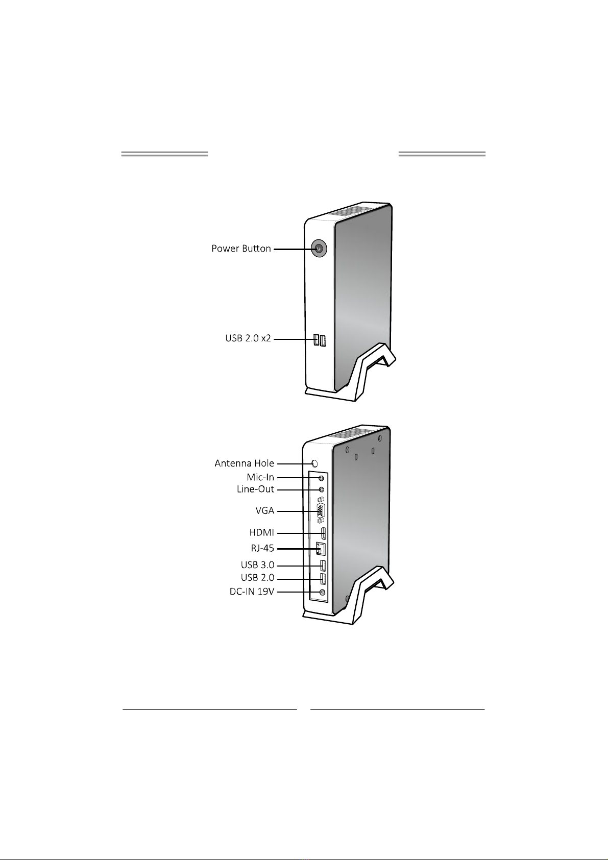
Rear I/O
DC jack (19V DC-in) 1x
USB 3.0 port 1x
USB 2.0 port 1x
RJ-45 Gigabit Lan port 1x
HDMI connector 1x
VGA connector 1x
Line-Out 1x
Mic-In 1x
Front I/O
USB 2.0 port 2x
Power on button 1x
Environment
Operation Temperature 0°C ~ 40°C (32°F ~ 100°F)
Storage Temperature -20°C ~ 60°C (-4°F ~ 140°F)
Relative Humidity 20% ~ 80% non-condensing
Power Supply 19V/45W
OS Support
Windows 7 / 8 / 8.1
Biostar reserves the right to add or remove support for any OS with or without notice.
Mounting
Foot stand
VESA 75/100 Mount Bracket (Optional)
Dimension 210mm (L) x 40mm (W) x 185mm (H)
Weight 0.8 kg
Regulatory
Compliance CE/FCC
iDEQ-T1 IN294KT1 Setup Manual
3
Getting to Know Your System
Front Panel
Rear Panel
iDEQ-T1 IN294KT1 Setup Manual
4
Chapter 2: System hardware installation
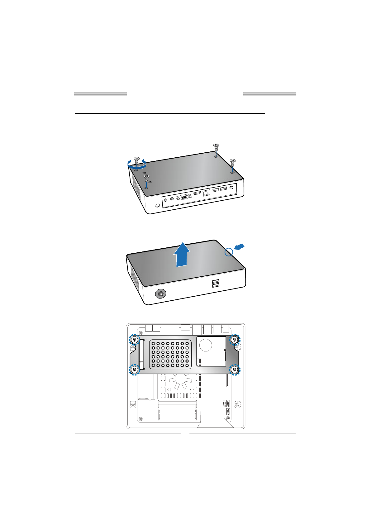
Disassembling the Cover
1. Loosen four screws on the bottom cover, then turn the system over.
2. Place the tip of your fingernail into the tiny gap between the cover and the
chassis, then pull up the cover.
3. Loosen four screws of HDD Bracket.

iDEQ-T1 IN294KT1 Setup Manual
5
4. After removing the HDD bracket, you will see the system board.
A. Installing WiFi Module
Insert WiFi module into mini PCIe slot and fasten screw. Connect antenna line to
“MAIN” on the WiFi module.
Note: Wi-Fi module sold separately
B. Installing Memory Module (1.35V/1.5V)
Insert memory module into SODIMM socket at backside of motherboard.
Note: The DIMM must be installed to DIMMA1 slot first.

iDEQ-T1 IN294KT1 Setup Manual
6
C. Installing a 2.5 inch HDD
1. Fasten HDD bracket with HDD.
2. Connect the SATA cable to the HDD and system board.
3. Screw the HDD bracket back to the system.
iDEQ-T1 IN294KT1 Setup Manual
7
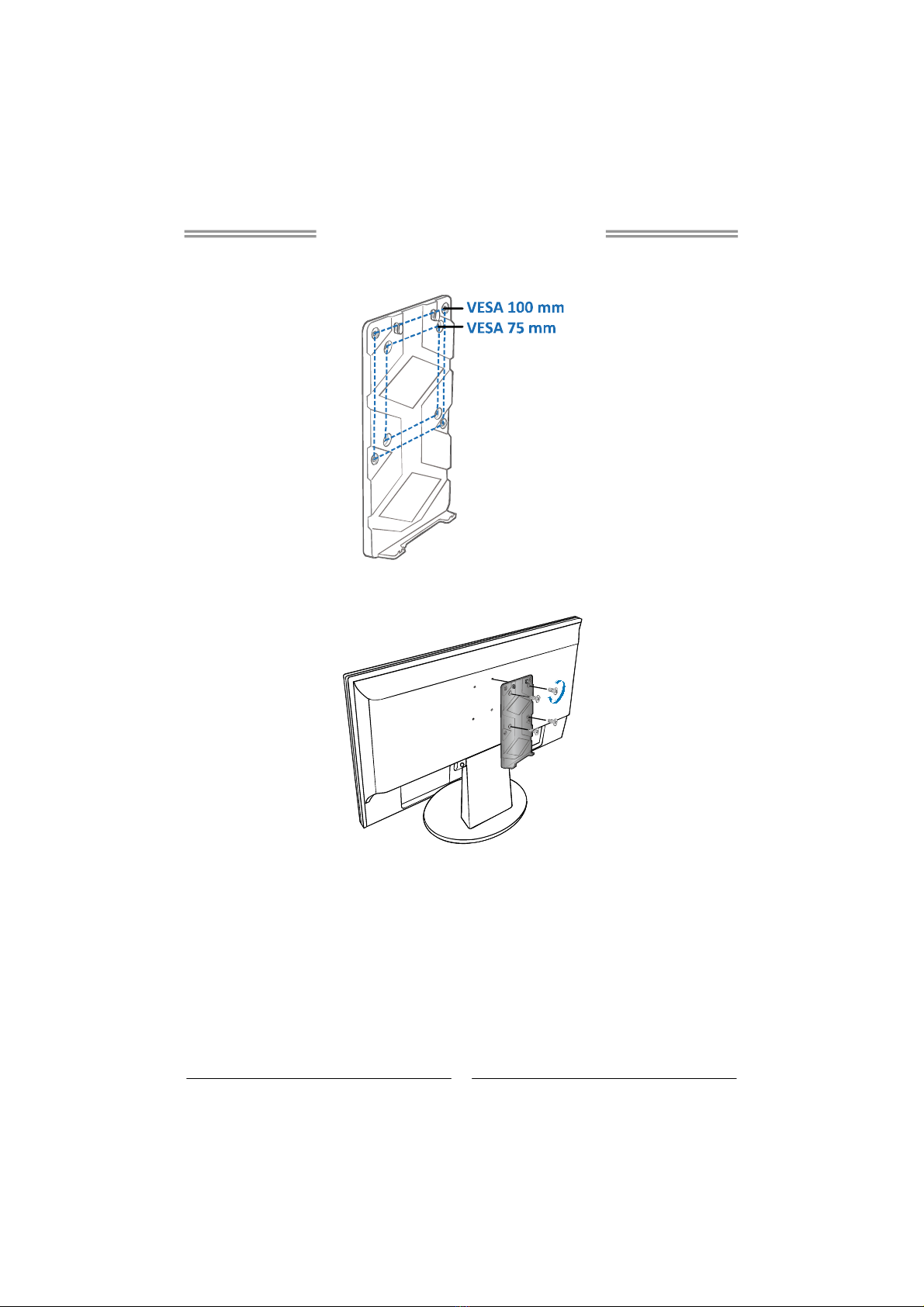
VESA Bracket (Optional)
1. The mounting kit has either the VESA 75 mm or 100 mm mounting pattern.
2. Secure the VESA mounting bracket to your monitor with four screws.
3. Place your PC on VESA bracket and make sure the PC is hooked by the
VESA mounting bracket.

iDEQ-T1 IN294KT1 Setup Manual
8
Antenna
Fasten antenna to the connector.
Note: After the system assembly, please place the rubber stand to each screw
hole.
Table of contents
Other Biostar Desktop manuals

Biostar
Biostar iDEQ 210M User manual

Biostar
Biostar IDEQ 210V User manual

Biostar
Biostar IDEQ 200S User manual

Biostar
Biostar IDEQ 210P User manual

Biostar
Biostar IDEQ 200T User manual

Biostar
Biostar 200A-M-EI User manual

Biostar
Biostar 210A User manual

Biostar
Biostar iDEQ-T1 IN2940T1 User guide

Biostar
Biostar IDEQ 200N User manual

Biostar
Biostar IDEQ C1 User manual


