
Yamatake DIGITRONIK SDC10 User manual

No. CP-UM-1703E
DIGITRONIK
Digital Indicating
Controller
SDC10
User’s Manual
Index
Chapter 1 NAMES & FUNCTIONS OF PARTS ..... 1
Chapter 2 STRUCTURE ........................................ 2
Chapter 3 MOUNTING ........................................... 3
Chapter 4 WIRING ................................................. 6
Chapter 5 INITIAL SETTINGS ............................... 9
5-1 Overall Operation Flow ............................... 10
5-2 Setup Items ................................................ 11
5-3 Parameter Settings ..................................... 18
5-4 Event Settings ............................................ 21
5-5 SP Setting .................................................. 21
Chapter 6 TUNING...............................................24
6-1 Selecting the Control Method ..................... 24
6-2 Self-tuning .................................................. 24
6-3 Cautions During Self-tuning ........................ 25
6-4 Auto-tuning ................................................ 26
6-5 Control Troubleshooting ............................. 27
Chapter 7 SPECIFICATIONS .............................. 28
Chapter 8 ALARM CODES ..................................30
Chapter 9 MAINTENANCE ..................................31
SDC10 Setup Worksheet ......................................... 32
Thank you for purchasing the DIGITRONIK Digital Indicating Controller SDC10.
This manual contains information for ensuring correct use of the DIGITRONIK
Digital Indicating Controller SDC10. It also provides necessary information
for installation, maintenance and troubleshooting. This manual should be read
by those who design and maintain devices and operator control panels that
use the DIGITRONIK Digital Indicating Controller SDC10. Be sure to keep
this manual nearby for handy reference.
Note that incorrect wiring of the SDC10 can damage the SDC10 and lead
to other hazards. Check that the SDC10 has been correctly wired before
turning the power ON.
Before wiring, or removing/mounting the SDC10, be sure to turn the power
OFF. Failure to do so might cause electric shock.
Do not touch electrically charged parts such as the power terminals. Doing
so might cause electric shock.
Do not disassemble the SDC10. Doing so might cause electric shock or
faulty operation.
This product has been designed, developed and manufactured for general-purpose
application in machinery and equipment.
Accordingly, when used in applications outlined below, special care should be taken to
implement a fail-safe and/or redundant design concept as well as a periodic maintenance
program.
•Safety devices for plant worker protection
•Start/stop control devices for transportation and material handling machines
•Aeronautical/aerospace machines
•Control devices for nuclear reactors
Never use this product in applications where human safety may be put at risk.
This manual uses the following symbols to ensure safe operation of this controller:
i
RESTRICTIONS ON USE
REQUEST
Ensure that this User's Manual is handed over to the user before the
product is used.
Copying or duplicating this User's Manual in part or in whole is forbid-
den. The information and specifications in this User's Manual are sub-
ject to change without notice.
Considerable effort has been made to ensure that this User's Manual is
free from inaccuracies and omissions.
If you should find any inaccuracies or omissions, please contact
Yamatake Corporation.
In no event is Yamatake Corporation liable to anyone for any indirect,
special or consequential damages as a result of using this product.
©1995 Yamatake Corporation ALL RIGHTS RESERVED
WARNING
CAUTION
Warnings are indicated when mishandling the SDC10
might result in death or serious injury to the user.
Cautions are indicated when mishandling the SDC10 might
result in minor injury to the user, or only physical damage
to the SDC10.
WARNING
ii
CAUTION
Do not operate the keys with a propelling pencil or sharp-tipped object.
Doing so might cause faulty operation.
In addition to the standard ON/OFF and PID controls, the SDC10 is also
equipped with self-tuning control which does not require setting control con-
stants. Self-tuning control ensures stable control even during changes in
SP values or during disturbances. This is achieved by monitoring and learn-
ing the characteristics of the control target to automatically output control
constants.
This function should be used according to the instructions given in the
manual.
Use the SDC10 within the operating ranges recommended in the specifica-
tions (temperature, humidity, voltage, vibration, shock, mounting direction,
atmosphere, etc.). Failure to do so might cause fire or faulty operation.
Do not block ventilation holes. Doing so might cause fire or faulty operation.
Wire the SDC10 properly according to predetermined standards. Also wire
the SDC10 using specified power leads according to recognized installa-
tion methods.
Failure to do so might cause electric shock, fire or faulty operation.
Do not allow lead clippings, chips or water to enter the controller case.
Doing so might cause fire or faulty operation.
Firmly tighten the terminal screws at the torque listed in the specifications.
Insufficient tightening of terminal screws might cause electric shock or fire.
Do not use unused terminals on the SDC10 as relay terminals.
Doing so might cause electric shock, fire or faulty operation.
We recommend attaching the terminal cover (sold separately) after wiring
the SDC10.
Failure to do so might cause electric shock, fire or faulty operation.
Use the relays on the SDC10 within the service life listed in the specifica-
tions.
Continued use of the relays after the recommended service life has expired
might cause fire or faulty operation.
Use Yamatake Corporation's SurgeNon if there is the risk of power surges
caused by lightning.
Failure to do so might cause fire or faulty operation.

iii
SAFETY REQUIREMENTS
To reduce risk of electrical shock which could cause personal injury, follow all safety notices
in this document.
This symbol warns the user of a potential shock hazard where hazardous live voltages may be
accessible.
* If the controller is used in a manner not specified by Yamatake Corporation, the protection provided
by the controller must be impaired.
* Do not replace any component (or part) not explicitly specified as replaceable by your supplier.
* All wiring must be in accordance with local norms and carried out by authorized and experienced
personnel.
* A switch in the main power supply is required near the equipment.
* Provide delayed type (T) fuses having a rated power supply of 200mA and voltage of 250V for the
mains power supply wiring of this AC power supply controller. (IEC 127)
EQUIPMENT RATINGS
Supply voltage 100 to 240Vac (operating power voltage 85 to 264Vac)
Frequency 50/60Hz
Power consumption 7VA max.
EQUIPMENT CONDITIONS
Do not operate the instrument in the presence of flammable liquids or vapors. Operation of any electrical
instrument in such an environment constitutes a safety hazard.
Temperature: 0 to 50°C
Humidity: 10 to 90%RH (condensation not allowed)
Vibration: 2m/s2(10 to 60Hz)
Over-voltage category: Category II (IEC60364-4-443, IEC60664-1)
Pollution degree: 2
EQUIPMENT INSTALLATION
The controller must be mounted into a panel to limit operator access to the rear terminals.
Make sure that the I/O common voltage and the grounding voltage excluding the power voltage are
33Vrms max., 46.7V (peak) max. and 70Vdc max.
APPLICABLE STANDARDS
EN61010-1, EN50081-2, EN50082-2, EN61326
The CE supported model is the C10T type (panel type) only.
H
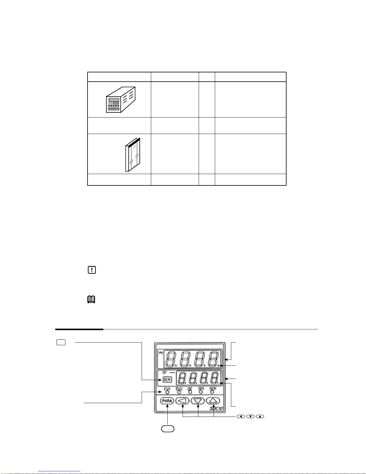
1
Hold this key down for at least 1
second to enable either of the
following operations.
•
•
•
•
Factory setting is key lock state.
Run (RUN)/ (READY)
Cancelation of event latch state
Auto-tuning start/stop
SP No. switching
key
EV1:
EV2:
OT:
SP1:
RDY:
Lights when event 1 is ON.
Lights when event 2 is ON.
Lights when the control output is ON.
Lights (or, blinks) when No.1 to No.3
SP is switched.
Lights when READY (control stop)
Mode LEDs
Displays PV values (current
temperature, etc.) or setup items
This LED blinks in the self-tuning mode.
Displays SP values (set
temperature, etc.) and other
parameter values.
This LED blinks in the auto-tuning mode.
Upper display
Lower display
keys:
Switches the display. Hold
down for at least 3 seconds
to switch modes.
key
PARA
RDY
Used for incrementing numeric
values and performing arithmetic
shift operations.
Unpacking
When unpacking the product, check that you have received all the items that you ordered.
The C10S type socket is optional.
After unpacking, handle the SDC10 and its accessories taking care to prevent damage or loss of parts.
Those using the communications function, should read the DIGITRONIK digital indicating controller
User's Manual SDC10 “Communications Function Manual”.
If an inconsistency is found or the package contents are not in order, immediately contact your dealer.
Conventions Used in This Manual
The following conventions are used in this manual.
Handling Precautions
: Handling Precautions indicate items that the user should pay attention to when
handling the SDC10.
Note :Notes indicate useful information that the user might benefit by knowing.
Name Catalog No. Q’ty Remarks
Body 1
Installation tool 81446403-001 1
(C10T type only)
User’s Manual CP-UM-1703E 1
Engineering Unit seal 1
See ■Model Selection
Guide on page 2.
This manual
Chapter 1 NAMES & FUNCTIONS OF PARTS
2
C10
T
(Note 1) S
0D
6D
T
R
L
A
D
00
01
(Note 2) 02
(Note 2) 03
(Note 2) 05
00
D0
Chapter 2 STRUCTURE
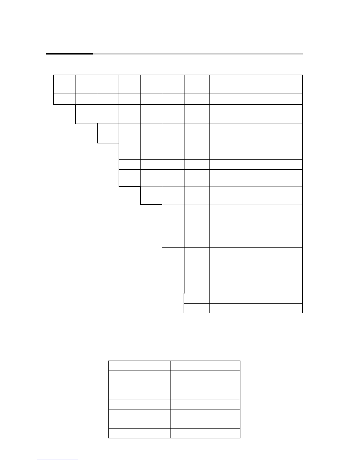
■Model Selection Guide
●Options
Basic
Model
No. Mounting Control
Output Power
Voltage Option Additional
Process-
ing
PV
Input Specifications
Panel mounting
Socket mounting
Relay output
Voltage pulse output (for SSR drive)
Thermocouple input (K, J, E, T, R, DIN
U, DIN L)
RTD (Pt100/JPt100)
DC voltage input
(0 to 1Vdc, 0 to 5Vdc, 1 to 5Vdc)
100 to 240Vac, 50/60Hz
24Vdc (no polarity)
None
2 event outputs
2 event outputs
2 non-insulated external switch inputs
1 current transformer input
2 event outputs
2 insulated external switch inputs
1 current transformer input
2 event outputs
RS-485 communications (CPL)
1 current transformer input
No additional processing
Provision of Inspection Sheet
(Note 1) A socket mounted model cannot be combined with 02, 03, 05 (option). The
socket is sold as an option.
CE is not covered on socket mounted models.
(Note 2) The current transformer is sold as an option.
Name Model No.
Current transformer QN206A (5.8mm hole dia.)
QN212A (12mm hole dia.)
Socket (C10S) 81446391-001
Mounting bracket 81446403-001
Hard cover 81446442-001
Soft cover 81446443-001
Terminal cover 81446464-001
3
Chapter 3 MOUNTING
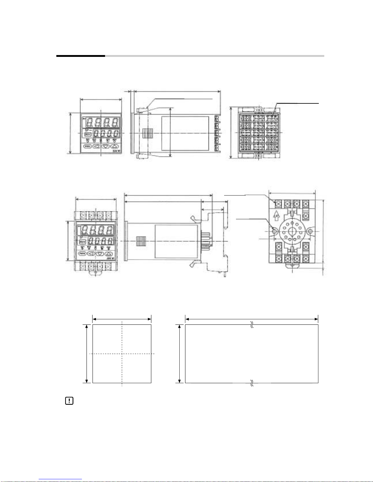
■External Dimensions
●C10T (panel mounted)
Mounting bracket (included) M3.5 terminal screw
Unit: mm
48
48
1014
□45
61
●C10S (with socket)
48
48
104
90.5 31
26.5
51
87 65
4
3
21
11
10
9
40
716.5
M3.5 terminal screw
Mounting hole
for 2-M4 screw
Socket (sold separately)
Model No.: 81446391-001
■Panel Cut-out Dimensions
45
-0
+0.6
45
-0
+0.6
(Nx48-2.5)
-0
+1
45
-0
+0.6
N is the number of mounted units
Handling Precautions
When three or more units are gang-mounted horizontally, the maximum allow-
able ambient temperature is 45°C.
4
CAUTION
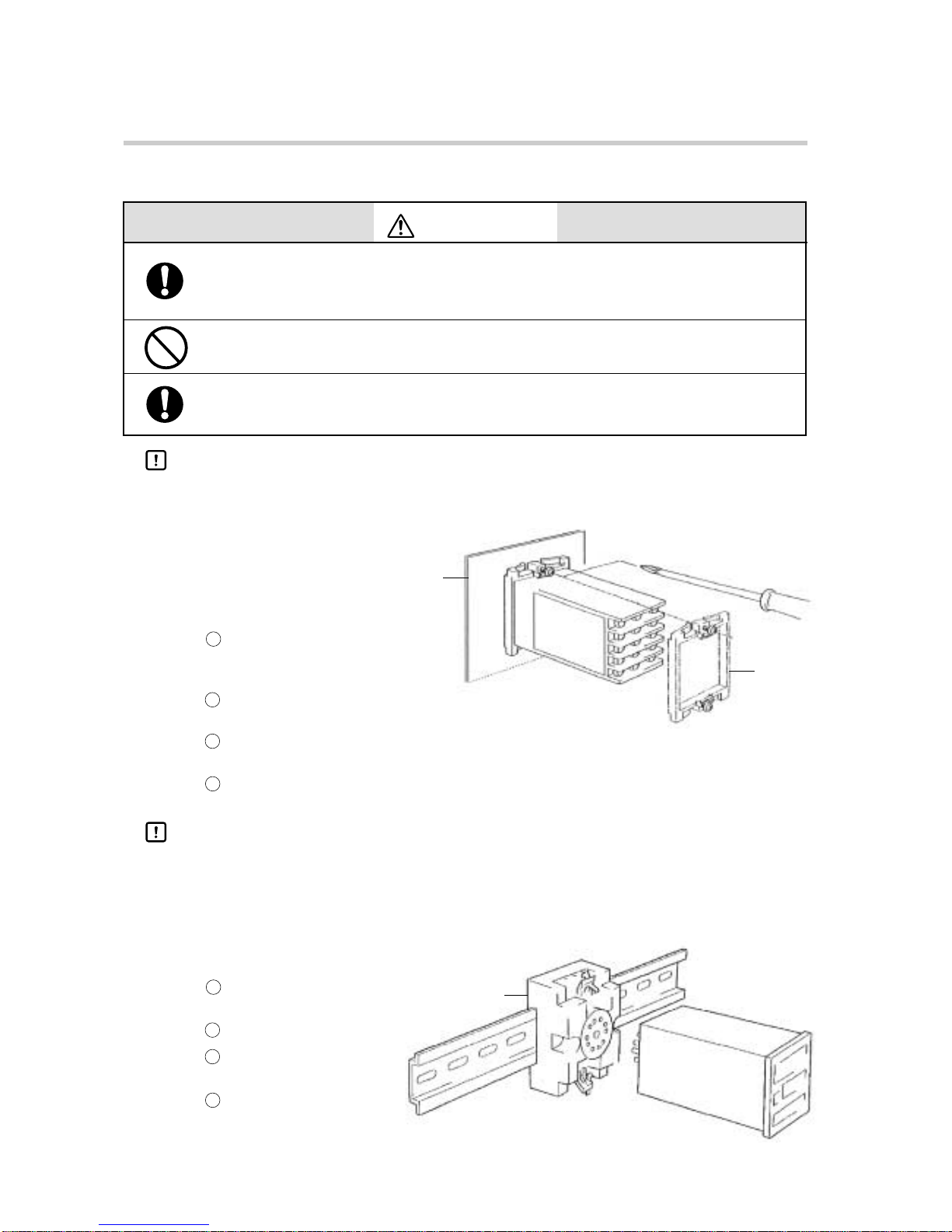
Press the controller against the mounting bracket to make sure that the bracket claws enter the
grooves of the controller.
Tighten the top and bottom screws. (When the screws touch the panel, turn the screws another half
turn.)
●C10T
●Required tools
Phillips screwdriver
Insert the controller into the
opening on the front side of the
panel.
Attach the mounting bracket at
the rear side of the panel.
■Mounting Procedure
Use the SDC10 within the operating ranges recommended in the specifica-
tions (temperature, humidity, voltage, shock, mounting direction, atmo-
sphere, etc.). Failure to do so might cause fire or faulty operation.
Do not block ventilation holes. Doing so might cause fire or faulty operation.
Be sure to attach the terminal cover (sold separately) after wiring the SDC10.
Failure to do so might cause electric shock, fire or faulty operation.
Handling Precautions
When three or more units are gang-mounted horizontally, the maximum allowable ambient
temperature is 45°C.
Panel
Mounting
Bracket
Socket
Handling Precautions
●Do not operate the keys with a propelling pencil or sharp tipped object. Be sure to mount this
controller on a panel. Cover terminals to prevent electric shock.
An optional terminal cover is provided. (model No.: 81446464-001)
●Do not overtighten the screws to prevent deformation of the front panel.
●C10S Mount the socket in the panel
using a DIN rail or screws.
Wire the socket.
Insert the body of the control-
ler into the socket.
Insert the clasps at the top and
bottom of the socket into the
holes of the controller body to
firmly secure it to the socket.
Chapter 3 MOUNTING
1
2
3
4
1
2
3
4
5
■Location
Do not install the controller in locations where it is:
• subject to extreme temperature and humidity
• subject to sulfuric or corrosive gases
• subject to dust or oil smoke
• subject to direct sunlight, or splashing by rain or water
• subject to mechanical vibrations and shock
• subject to high-voltage lines, welding machines and sources of electric noise
• less than 15 m from high-voltage ignition devices
• subject to electromagnetic fields
• subject to flammable liquids or vapor
■Removing the SDC10T Case
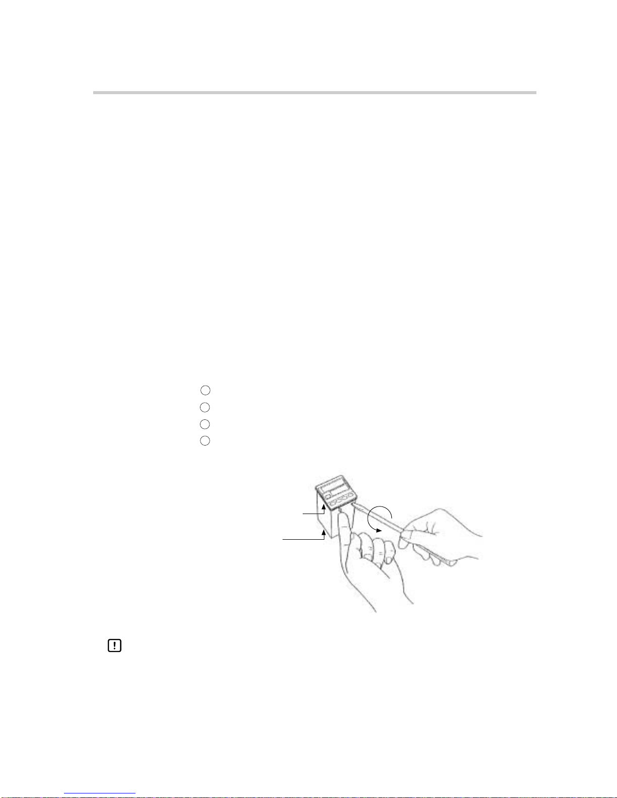
The following instructions show how to remove the SDC10T body from the case. This
has to be carried out only when the controller is to be replaced:
●Required tools
Small standard screwdriver
Press the claw on the lower left side of the mask bezel with your finger.
Insert the screwdriver into the groove between the mask bezel and the controller body.
Press the claw while turning the screwdriver.
Take hold of the front end of the body as it is forced out of the case and pull it out.
Mask bezel
Case
Handling Precautions
●Turn the power OFF before carrying out the above procedure.
●In the case of the socket model (C10S), internal components cannot be drawn
out.
Chapter 3 MOUNTING
1
2
3
4
6
CAUTION
Wire the SDC10 properly according to predetermined standards. Also wire
the SDC10 using specified power leads according to recognized installa-
tion methods. Failure to do so might cause electric shock, fire or faulty
operation.
Do not allow lead clippings, chips or water to enter the controller case.
Doing so might cause fire or faulty operation.
Firmly tighten the terminal screws at the torque listed in the specifications.
Insufficient tightening of terminal screws might cause electric shock or fire.
Do not use unused terminals on the SDC10 as relay terminals.
Doing so might cause electric shock, fire or faulty operation.
We recommend attaching the terminal cover (sold separately) after wiring
the SDC10. Failure to do so might cause electric shock, fire or faulty opera-
tion.
Use the relays on the SDC10 within the service life listed in the specifica-
tions.
Continued use of the relays after the recommended service life might cause
fire or faulty operation.
Use Yamatake Corporation’s SurgeNon if there is the risk of power surges
caused by lightning.
Failure to do might cause fire or faulty operation.
Make sure all wiring is correct. Incorrect wiring may damage connected
equipment.
The controller does not operate until six seconds after the power has been
turned ON. Special arrangements must be made when the relay output
from the controller is to be used as an interlock signal.
When a ground type thermocouple must be used and an external switch
input is required, PV readout error caused by sneak path current may oc-
cur. Select the insulated external switch input model (option code 03).
Chapter 4 WIRING
■Terminal Array and Wiring
Before wiring, or removing/mounting the SDC10, be sure to turn the power
OFF. Failure to do so might cause electric shock.
Do not touch electrically charged parts such as the power terminals. Doing
so might cause electric shock.
WARNING
Table of contents
Other Yamatake Controllers manuals


Popular Controllers manuals by other brands

Digiplex
Digiplex DGP-848 Programming guide

YASKAWA
YASKAWA SGM series user manual

Sinope
Sinope Calypso RM3500ZB installation guide

Isimet
Isimet DLA Series Style 2 Installation, Operations, Start-up and Maintenance Instructions

LSIS
LSIS sv-ip5a user manual

Rockwell Automation
Rockwell Automation 1769-L31 installation instructions


