Wicked Fun Hobbys Slicko User manual

Slicko 32” 3D EPP Plane
Instruction Manual
Specifications: Equipment Required:
Wingspan: 32 ½” Servos: 1x8-9g servo & 2x5- g servos
Length: 33 ½ “ Radio: 4+ channel w/light weight receiver.
Weight: AUW .5oz-7.5oz Motor: 18g–25g 1500–1900kv 50+ Watt.
Construction: Durable EPP, Wood & Carbon Fiber ESC: 8A – 12A
COG: 5/8”-1” Behind the Wing Spar Battery: <35g 330–500mAh 20C+ 2S or 3S.
Build Time: 1-4hrs Propeller: 8”-9” Direct Drive or Slow Fly.
Supplies/Tools:
Glue (Welder or Foam-Tac & CA recommended) Soldering Iron and Solder
Steel Ruler 24”-3 ” Wax or Parchment Paper or Plastic sheet
Small Weights or food/drink cans Paint or permanent markers (optional)
Triangle Flat Level work surface
Hobby Knife Heat Gun or Lighter (optional)
Airframe Construction:
Note: It is critical that you build on a perfectly flat work surface to insure a straight build. Use
wax, parchment paper or plastic under the glued surfaces to keep them from sticking to your
work surface.
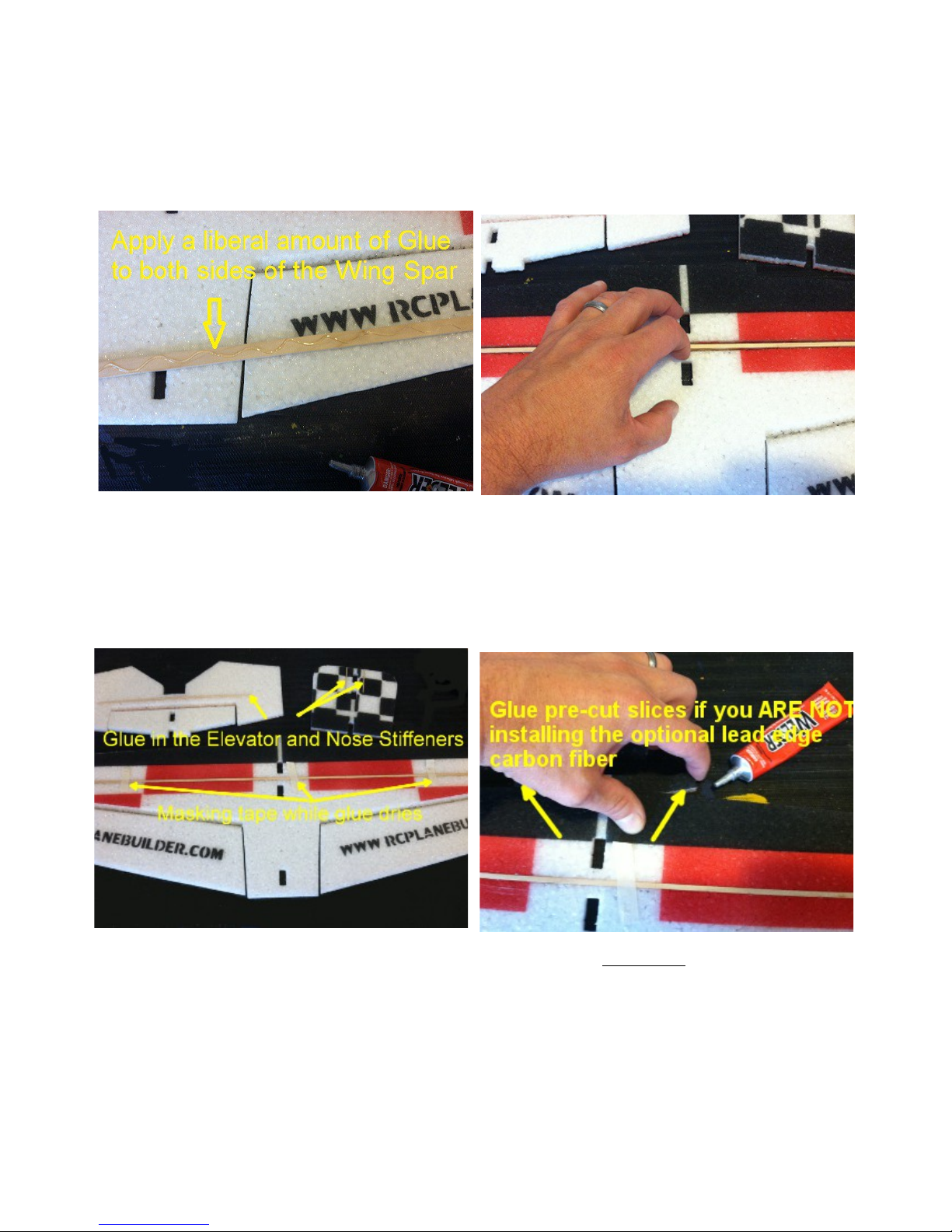
Step 1 – Apply glue liberally to both sides of Step 2 – Place spar in the wing squeeze the
the 29” wood Wing Spar. foam against the spar to spread the glue on
to the foam. If you are using a contact
adhesive such as Welder you can spread the
joint back apart and hold for 30- 0 seconds
before re-applying. This will allow the glue to
setup more quickly.
Step 3 – Glue in the 10” wood elevator and Step 4 – If you ARE NOT installing the
2- 2” nose stiffeners. Insure that the nose optional carbon fiber lead edge pieces.
stiffeners sit flush with the front of the Glue the cut slices on either side
fuselage. of the nose where it meets the wing.
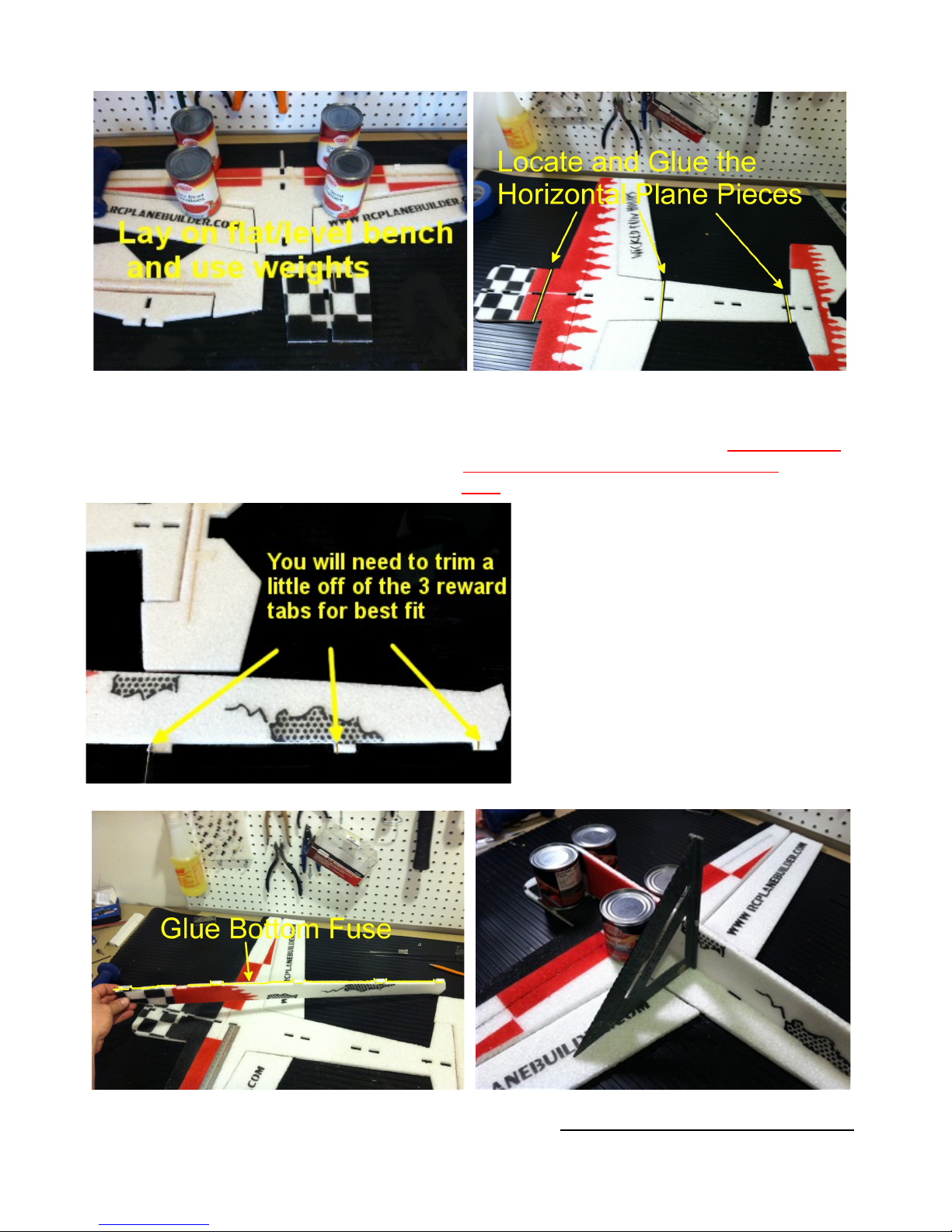
Step 5 – Lay all pieces on your flat/level Step 6 – Layout the horizontal plane pieces and
work surface. Use food cans or other glue together making sure they are aligned
weights to hold them flat so that they don't correctly. Allow the glue to dry. NOTE: Make
dry warped. Let the glue dry. sure all hinge bevels are on the same
side.
Step – Locate the bottom vertical
fuselage and trim the 3 most rearward
tabs about 1/8” as shown. Trial fit the
bottom fuse into the horizontal fuse to
insure a good fit. Make sure the front of
the vertical fuse lines up well with the
front of the horizontal fuse where the
motor will mount. NOTE: Make sure
when you glue that you are gluing the
bottom fuselage to the bottom of the
plane. The cut hinge bevels should be
facing up.
Step 8 – Apply a liberal bead of glue to the Step 9 – Use an angle to insure that the fuselage
bottom vertical fuselage, press down to the is square. Make sure that the vertical fuselage
horizontal fuselage weight with food cans. is glued well to the horizontal along the length
NOTE: Use weights along the fuse, wing and tail sections on your flat/level surface while the
glue sets up to insure a straight build.
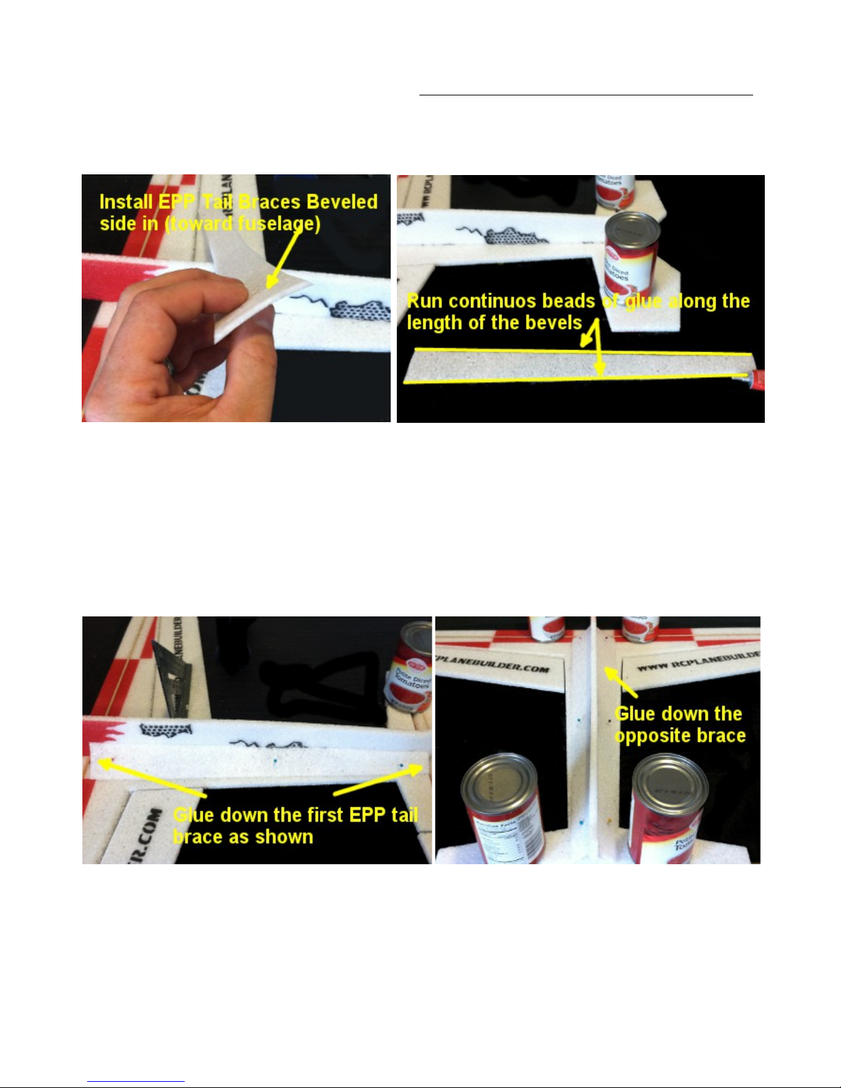
Step 10 – Place weights on the wing tips and tail on your flat works surface. Place your first
EPP brace bevel side up and run continues beads on both bevels (above right). Place the first
brace (below left), you can use push pins to help hold it down. Continuously press the glue
joints down every couple of minutes to insure that you have a good bond down the whole
length of the brace to the fuselage. Use a 45 degree angle to insure that you do not warp the
vertical fuselage. Repeat for the second side (below right). NOTE: it is important to make sure
the braces are glued down along the whole length of the fuselage for best performance.
When installing make sure your vertical fuselage remains straight.
NEXT: If you are installing the optional carbon fiber reinforcement kit and/or landing
gear jump forward to section 13/15 and complete the installation steps then return
here.

Step 11 – Fit your aileron servo into the cut servo hole and check for fit. It should fit snugly.
Trim as necessary as shown above. Once you have a good fit you can thread the wire
through the hole so that the connector is on the side with the carbon fiber truss bracing. Now
put a small dab of glue on the servo tabs to hold it in.
Step 12– Trim 1/8” off of the front of the
3 rearward tabs on the top fuselage.
When installed the front of the top
fuselage should be flush with the
horizontal fuselage where the motor
mounts.
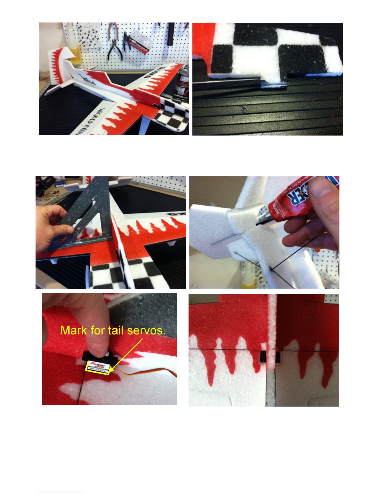
Step 13 – Temporally place the top fuselage and check for fit. If it does not sit flush trim any
tabs as necessary (above right). Glue on the top fuselage and adjust to make sure it is square
(below left). Glue the back tail piece (below right).
Step 14 – Mark the foam directly on either side of the fuse and right behind the wing spar and
cut for your tail servos. Cut the holes smaller than the servos so that they are a tight fit (above
right).
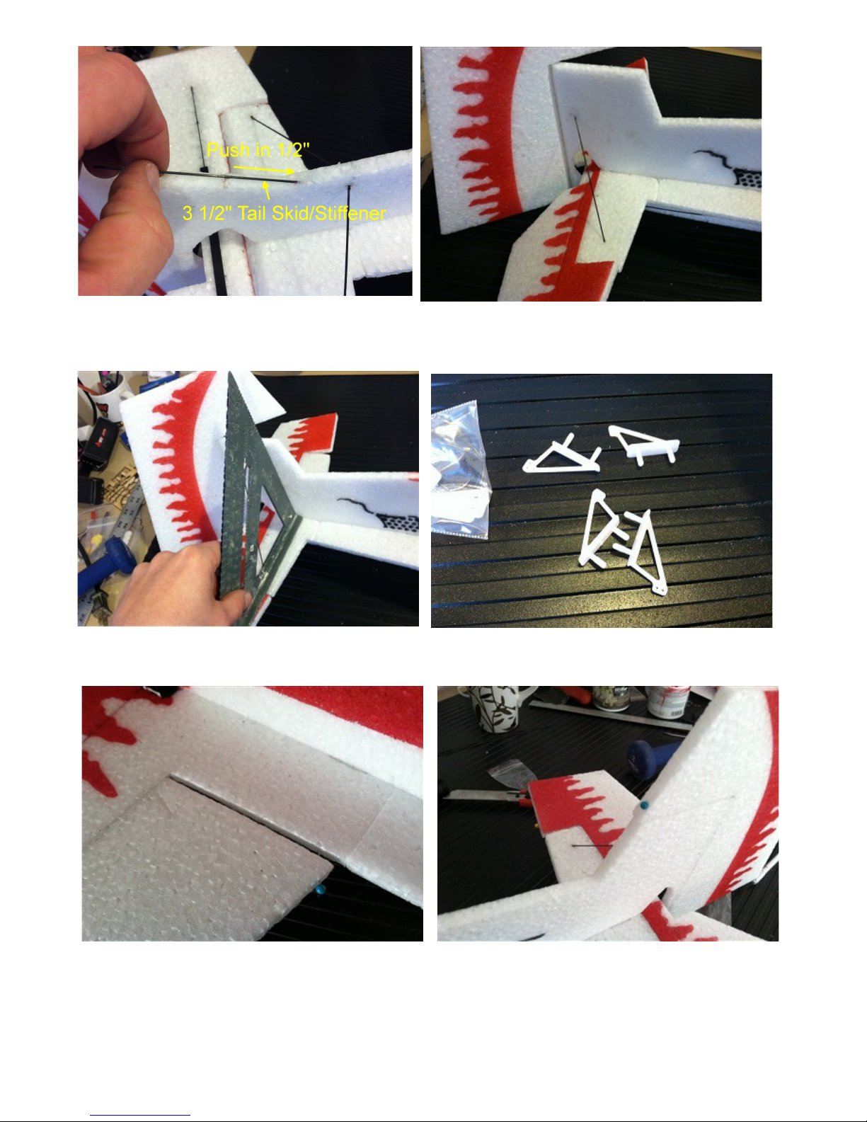
Step 15 – Locate 3 ½” 1.5mm carbon tail skid Step 16 – Locate the final 4 ½” vertical
/tail stiffener. Press the stiffener ½” into the stabilizer brace and glue in and check for
EPP and glue down the rod to the tail. Square (picture below).
Step 1 – Locate the 4 control horns as pictured (above right). Pin or tape the ailerons,
rudder and elevator so they are level as shown below.

Step 18 – Apply glue to the control horn base and posts (above left). Glue the control horns
into the cut slots in the ailerons, elevator and rudder. Slide the horns so that the push-rod
holes line up over the center of the hinge (above right). Save the 4 horn back plates as they
will be used for push-rod stand off guides later. NOTE: All horns should be glued on the flat
hinge side opposite of the cut bevels.
Step 19 – Locate and install the extended Step 20 – Straighten the servo arm so that
aileron servo arm. If the servo arm doesn't the push rods will be even lengths. Assemble
fit on your servo you can flip it over and one of your aileron push rod which includes
CA glue it to your existing servo arm and a 5 ¾” 1.5mm rod, 1 z-bend, 1 adjustable
heat shrink it. z-bends and 2 pieces of shrink tube. Lightly
sand each end of the carbon fiber push rod and
the z-bends where they will connect. NOTE:
Place a piece of cardboard or card-stock around
the control horn so that you do not apply heat
directly to the EPP when shrinking as pictured.
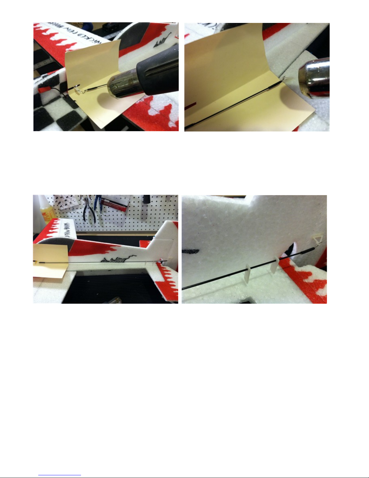
Step 19 – Move the shrink tube over and place a couple drops of CA on the z-bend/control
rod. Quickly slide the shrink tube back over and shrink with a heat gun, lighter or soldering
iron. Once cooled you can hit the ends of the shrink tub with another drop of CA. NOTE:
Make sure you always have a barrier between the heat gun/soldering iron and the EPP. Never
apply heat from the heat gun or soldering iron directly to the EPP or it will get damaged.
Step 20 – Locate the longer of the 2 tail push rods for your rudder. Install 2 of the plastic
stand-offs pictured (above right) over the rod and install z-bends and shrink tube as you did
with the aileron push rods. Make sure your servo control horn is 45 degrees with the vertical
fuselage. Install the elevator push rod in the same way. Make sure to slide the 2 remaining
plastic stand-offs on the elevator push rod. NOTE: Again, make sure you use card-stock or
cardboard between the heat source and the EPP so that it does not damage the EPP foam.

Step 21 – Cut small slices ¾ through the foam to install the stand-offs as shown above. Make
sure that they line up with the push rod so that the rod does not bow excessively. The back
stand-offs for the rudder is on the vertical fuse and the front one is on the horizontal fuse . On
the elevator push rod both stand-offs will be on the horizontal fuse.
Step 22 – Hook up your radio and ESC per the manufactures instructions. Temporally place
at either side of the fuselage as shown. Note how I routed the battery connector through a
small slit in the EPP to the top of the fuselage where I will mount my battery. Don't attach your
RX or ESC to the fuselage yet, we may need to move them to get the COG correct.
Table of contents


