WEG SSW-05 Plus Series User manual

SOFT-STARTER
Arrancador Suave,
Chave de Partida Soft-Starter
Motors | Automation | Energy | Coatings
User’s Guide
Guia del Usuario
Manual do usuário

ENGLISH
SUMMARY - English
1. Safety Instructions .......................................................................................................................................03
2. What is the SSW-05 Plus Soft-Starter .........................................................................................................03
3. How to identify the SSW-05 Plus .................................................................................................................03
4.TechnicalData .............................................................................................................................................04
5. SSW-05 Plus Description ............................................................................................................................05
6.Table ofPowers/Currents/PowerWiring (copper wireat70°C(158oF)) ......................................................05
7.TableofConnectorTighteningTorque ...........................................................................................................05
8. Capacity of the Power Supply Line...............................................................................................................06
9. Table of Fuses and Contactors .....................................................................................................................06
10.Dimensions ................................................................................................................................................06
11. SSW-05 Plus Installation and Connection ..................................................................................................07
12. SSW-05 Plus Setting .................................................................................................................................08
13.Operation of the DigitalRelayOutputs........................................................................................................10
14. Protections and Displays ...........................................................................................................................11
15.OverloadProtection ....................................................................................................................................12
16.Reset .........................................................................................................................................................13
17. Faults and Possibles Causes.....................................................................................................................13
18.Solvingthemostfrequent problems ............................................................................................................15
19. SSW- Options andAccessories .................................................................................................................15
20.Table of Parameters (for serial communication/HMI-SSW05-RS) ................................................................20
21.Errorcode and description (for serialcommunication/HMI-SSW05-RS) ....................................................21
22.DetailedParameterDescription(forserialcommunication/HMI-SSW05-RS)...............................................21
23.AppendixforCE Conformance ....................................................................................................................28
24.EUDeclarationofConformity......................................................................................................................29
Warranty SSW-05 Plus....................................................................................................................................30

ENGLISH
Note: 1) The SSW-05 Plus electronic Soft-Starter has been designed to drive three-phase induction motors
applied to light duty loads, such as centrifugal pumps, small fans and screw compressors.
If the Soft-Starter shall be applied on heavy duty loads, please contact WEG.
2) The serial communication is available in the SSW-05 with software versions greater than V2.00.
The manual of the serial communication (0899.4587) is available for download on the website
www.weg.com.br.
With the serial communication is possible:
a) to connect the Soft-Starter in an equipment network, like PC, PLC, and others;
b) to use with SuperDrive software (417102505) for Microsoft Windows, allowing the SSW-05
programming and operation;
c) to use the remote HMI (human machine interface) for SSW-05 programming and operation.
1.SAFETYINSTRUCTIONS:
Always disconnect the power supply from the equipment before attempting any maintenance work.
Personnel must review this entire Manual before attempting to install and operate the SSW-05 Plus Soft-Starter.
Only qualified personnel should plan or implement the installation, start-up, setting, operation and maintenance of
thisequipment.
2. WHAT IS THE SSW-05 PLUS SOFT-STARTER:
TheSSW-05Plus Soft-Starter allows smooth start/stopofthree-phase induction motors.
3. HOW TO IDENTIFY THE SSW-05 PLUS:
SSW05
Soft-Starter
WEG Series 05
0003
Rated Output
Current:
0003 = 3A
0010 = 10A
0016 = 16A
0023 = 23A
0030 = 30A
0045 = 45A
0060 = 60A
0085 = 85A
T
Three-phase
Power Supply
2246
Power Supply
Voltage:
2246 =
220 to 460V
4657 =
460 to 575V
P
Manual
Language:
P= Portuguese
E= English
S= Spanish
P
SSW-05
Version:
P= Plus
Z
End of Code
Series: SSW-05 Plus
Software Version: 2.0X
0899.4668 /5
INSTALLATION
AND OPERATION
MANUAL
Example:Thecode SSW050010T2246PPZ means a 10ASSW-05Plus,three-phasepower supply in the range
from220to 460V,manualinPortuguese,PLUS version.

ENGLISH
Model
AC Input Power Control Voltage (A1 andA2)
Power supply
(R/1L1, S/3L2, T/5L3)
Settings
Pedestal Voltage
Acceleration Time
Deceleration Time
Motor Current
Diagnostics
StartDuty Maximum Number of Starts
per hour
Starting Cycle
Digital Inputs
(90...250Vac 6mA)
Relay
Outputs (1A250Vac)
Communication Temperature
Ambient Humidity
Altitude
Degree of Protection
Polution Degree (UL508)
Mounting Fastening
Enclosure
Electromagnetic Compatibility
(EMC)
Low Voltage
SSW-05 Plus
90 ... 250Vac 50/60 Hz (+/- 6Hz)
200 mA
220 ...460 Vac (+10%,-15%) 50/60 Hz (+/- 5Hz) 3φ
460 ... 575 Vac (+10%,-15%) 50/60 Hz (+/- 5Hz) 3φ
30 ... 80% UN
1 ... 20 s
Off ... 20 s
30 ... 100% IN
4 ( 1 start every 15 minutes)
3 x IN during 10 seconds
0 ... 55°C (32...131°F)
5 ... 90% Non Condensing
0 ... 1000m (up to 13,200 ft (4000m) with
10% output current derating/1000m)
IP 00 (Chassis)
2
DIN 35mm rail or M4 fastening bolts
Molded plastic box
Class A (industrial use)
IEC 60947-4-2 Standard
UL 508 / IEC 60947-4-2
4.TECHNICALDATA:
Standards
Motor Overload Protection
Incorrect Phase Sequence
Phase Loss
Immediate Overcurrent
Locked Rotor
Thyristor Overload
Immediate Overload at
By-pass Relay
Overcurrent before By-pass
Frequency out of Tolerance
Internal By-pass Relay
Contact is open
Undervoltage at control
voltage
DI1 – Enable/Disable Function
DI2 – Reset Function
Operation Function (13 – 14/23)
Full Voltage Function (14/23 – 24)
Serial Interface (RS232C)

ENGLISH
5. SSW-05 PLUS DESCRIPTION:
7.TABLEOFCONNECTOR TORQUESETTINGS:
SSW-05 Plus
Size
1
2
Torque-Power Terminals
(R, S, T, U, V and W)
Nm (lb-in)
3.0 (32.7)
5.5 (60.0)
Nm (lb-in)
0.5 (4.5)
0.5 (4.5)
Torque of
Electronics Terminal
* Accordingto able 45.2, UL508.
** Valid for Standard 4 pole WEG motors.
6. TABLE OF POWERS / CURRENTS / POWER WIRING (COPPER WIREAT 70°C (158OF)):
Model
SSW-05.3
SSW-05.10
SSW-05.16
SSW-05.23
SSW-05.30
SSW-05.45
SSW-05.60
SSW-05.85
Rated
Current
3A
10A
16A
23A
30A
45A
60A
85A
220V...240V*
HP kW
0.75 0.55
3 2.2
5 3.7
7.5 5.5
10 7.5
15 11
20 15
30 22
380V...415V*
HP kW
1.5 1.1
5 3.7
7.5 5.5
10 7.5
15 11
25 18.5
30 22
50 37
440V...480V*
HP kW
1.5 1.1
5 3.7
10 7.5
15 11
20 15
30 22
40 30
60 45
Power Wiring
mm2(AWG)
0.75 (18)
1.5 (16)
4 (12)
6 (10)
10 (8)
16 (6)
25 (4)
35 (2)
Size
1
2
525V**
kW
1.5
5.5
11
15
18.5
30
45
55
575V*
HP
2
7.5
10
20
25
40
50
75
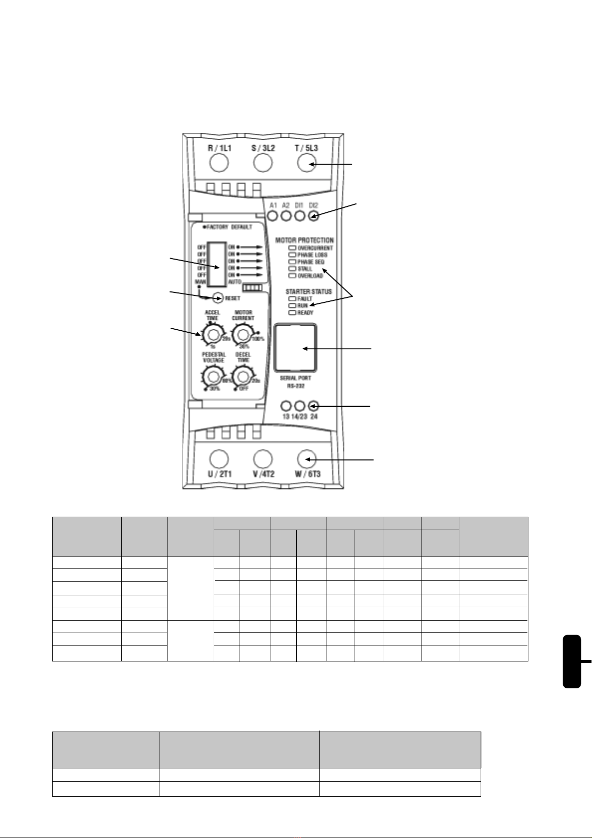
Setting Trimpots
Reset Button
Dip-switch for Protection
Enable
Three-phase Input Power Supply
Reset (DI2)
MotorEnable/DisableCommand(DI1)
Electronics Power Supply (A1 and A2)
SSW-05 Plus Status LEDS
Relay Output (13, 14/23 and 24)
Output to motor
Connector for Serial
Interface or HMI

ENGLISH
8. CAPACITY OF THE POWER SUPPLYLINE:
The SSW-05 Plus is suitable to be used in circuits that can not supply more than XARMS (according to table below)
symmetric Ampères, Y Volts maximum:
SSW-05 Plus
Model
3A
10A
16A
23A
30A
45A
60A
85A
Y = 220- 575V
X (kA)
5
5
5
5
5
5
5
10
9. TABLE OF FUSESAND CONTACTORS (SEE ITEM 11):
SSW-05 Plus
Model
3A
10A
16A
23A
30A
45A
60A
85A
Contactor
(K1)
CWM09
CWM12
CWM18
CWM25
CWM32
CWM50
CWM65
CWM95
Fuse
(F1,F2,F3)
Type D 10A
Type D 16A
Type D 25A
Type D 35A
Type D 50A
Type D 63A
Type NH 100A
Type NH 125A
Fuse
(F11, F12,F21)
Type D6A
10.DIMENSIONS:
Notes:
1) The SSW-05 Plus can be fixed on DIN 35mm rail.
2) In the case of fixing through M4 screw, the torque should not be greater than 0.2 Nm (1.77 lb in) for the upper
screws and 1.0 Nm (8.85 lb in) for the lower screws.
Size
1
2
Width L
mm (in)
59 (2.32)
79 (3.11)
Depth P
mm (in)
145 (5.70)
172 (6.77)
FixingA
mm (in)
51 (2.00)
71 (2.79)
FixingB
mm (in)
122 (4.80)
177 (6.17)
Fixing
M4 screw/ Rail
M4 screw/ Rail
Weight
kg (Lb)
0.74 (1.63)
1.67 (3.68)
HeightH
mm (in)
130 (5.11)
185 (7.28)
FixingD
mm (in)
61 (2.40)
99 (3.89)

ENGLISH
11. SSW-05 PLUS INSTALLATION AND CONNECTION:
11.1. Simplified Start/Stop on 230V/400 line:
11.2.Starting andStoppingusing ContactorandPushButtons:
The “T1” transformer is only required when the
line voltage is out of the range allowed for the
electronics supply (90 – 250Vac). For 400V,
use neutral conductor (N) and one phase.
230/400V Symbol Description
Fuse
Disconnecting Switch
(opens under load)
Transformer
N.O. switch
(with holding)
N.C. push button
(with automatic return)
N.O. push button
(with automatic return)
Contactor (coil)
Three-phase induction
motor
Symbol Description
Fuse
Disconnecting Switch
(opens under load)
Transformer
N.O. switch
(with holding)
N.C. push button
(with automatic return)
N.O. push button
(with automatic return)
Contactor (coil)
Three-phase induction
motor

ENGLISH
11.3. Start/Stop by using Push Button and Operation Function Relay of the SSW-05 Plus:
The “T1” transformer is only required when the
line voltage is out of the range allowed for the
electronics supply (90 – 250Vac). For 400V,
use neutral conductor (N) and one phase.
12. SSW-05 PLUS SETTING:
12.1. Pedestal Voltage Setting:
Set the pedestal voltage to a value that the motor starts to run as soon as run command is given by the SSW-05
Plus.
12.2. Setting of the acceleration ramp time:
Set the value so that the motor accelerates to the rated speed.
Note: Please consider that in the cases where rated SSW-05 Plus current is equal to the rated motor current,
the SSW-05 Plus can be operated, at maximum, during 10 seconds at 3 x IN.
Trimpot for the
pedestal
voltage setting
Trimpot for
the
acceleration
Ramptime
setting
Symbol Description
Fuse
Disconnecting Switch
(opens under load)
Transformer
N.O. switch
(with holding)
N.C. push button
(with automatic return)
N.O. push button
(with automatic return)
Contactor (coil)
Three-phase induction
motor
The dot
indicates the
factory default

ENGLISH
12.3. Setting of the deceleration ramp:
Thissettingshouldbe used only for decelerationofpumpsinordertoreduce hydraulic shocks. This setting mustbe
madeinorder to obtain thebestpumpperformance.
12.4. Setting of the Motor Current:
Thissettingdefinestheratioof the SSW-05 Plus currentandthedrivenmotorcurrent.Thesettingofthis value is very
important, since it defines the protection of the motor driven by the SSW-05 Plus. The setting of this function has
directinfluenceoverthefollowingmotorprotections: overcurrent, overload, locked rotor,phaseloss.
Trimpot for the
deceleration
Ramptime
setting
Calculationexample:
Used SSW-05 Plus: 30A
UsedMotor: 25A
Setting of the Motor Current = IMotor
ISSW-05 Plus
Setting of the Motor Current =25A
30A
Setting of the Motor Current = 0.833
Thus it must be set at 83%.
Trimpot for
the motor
current
setting

ENGLISH
13. OPERATION OF THE DIGITALRELAYOUTPUTS:
The relay of the Operation Function closes its N.O. contact (13-14/23) always when the SSW-05 Plus receives the
enable command. This contact is open only at the end of the deceleration ramp (when it is set via trimpot) or when
the SSW-05 Plus receives the disable command.
The relay of the Full Voltage Function closes the N.O. contact (14/23-24) always when the SSW-05 Plus applies
100%voltageto the driven motor.Thiscontactopenswhen the SSW-05Plus receives thedisablecommand.
t
t
t
Relay On
This manual suits for next models
8
Table of contents
Languages:
Other WEG Controllers manuals

WEG
WEG AVR-A-OPT-06 User manual

WEG
WEG SSW06 User manual

WEG
WEG PLC300 User manual

WEG
WEG SSW-05 User manual

WEG
WEG CP-D User manual

WEG
WEG WCD-SWU Series User manual

WEG
WEG GRT7-TR1 User manual

WEG
WEG SSW900-CAN-W User manual

WEG
WEG PLC500 Installation and operating instructions

WEG
WEG AVR-A-OPT-06 User manual
Popular Controllers manuals by other brands

Digiplex
Digiplex DGP-848 Programming guide

YASKAWA
YASKAWA SGM series user manual

Sinope
Sinope Calypso RM3500ZB installation guide

Isimet
Isimet DLA Series Style 2 Installation, Operations, Start-up and Maintenance Instructions

LSIS
LSIS sv-ip5a user manual

Rockwell Automation
Rockwell Automation 1769-L31 installation instructions