
Valet 710T User manual

Model 710T
Installation Guide
© 1999 Directed Electronics, Inc. Vista, CA N710T 10-99
®
®

2© 1999 Directed Electronics, Inc. Vista, CA
table of contents
What Is Included . . . . . . . . . . . . . . . . . . . . . 3
Installation Points To Remember . . . . . . . . . . 4
Wiring the Control Unit. . . . . . . . . . . . . . . . . 4
Primary Harness (H1), 12-pin Connector . . . . . 5
Primary Harness (H1) Wire Connection Guide. . 6
Plug-In LED and Valet/Program Switch . . . . . . 11
Harness 2 (H2), (+/-) Door Lock Outputs . . . 12
Door Lock Wiring Diagrams . . . . . . . . . . . . . 12
Type A Door Locks. . . . . . . . . . . . . . . . . . 12
Type B Door Locks. . . . . . . . . . . . . . . . . . 13
Type C Door Locks. . . . . . . . . . . . . . . . . . 14
Type D Door Locks. . . . . . . . . . . . . . . . . . 15
Type E Door Locks. . . . . . . . . . . . . . . . . . 16
Type F Door Locks . . . . . . . . . . . . . . . . . . 16
Transmitter/Receiver Learn Routine. . . . . . . . 17
To advance from one channel to another . . . 18
To exit learn routine . . . . . . . . . . . . . . . . 18
Transmitter Configurations. . . . . . . . . . . . . . 18
Standard Configuration. . . . . . . . . . . . . . . 18
OEM Style Configuration . . . . . . . . . . . . . . 19
Two Vehicle Operation With A
Single Transmitter. . . . . . . . . . . . . . . . . . . . 19
Operating Settings Learn Routine . . . . . . . . . 20
To access another feature . . . . . . . . . . . . . 21
To exit the learn routine. . . . . . . . . . . . . . 21
Features Menu . . . . . . . . . . . . . . . . . . . . . . 21
Feature Descriptions . . . . . . . . . . . . . . . . . . 22
Rapid Resume Logic . . . . . . . . . . . . . . . . . . 23
Master Dealer Remotes . . . . . . . . . . . . . . . . 23
Troubleshooting . . . . . . . . . . . . . . . . . . . . . 24
Bitwriter™, Code Hopping™, DEI®, Doubleguard®, ESP™, FailSafe®, Ghost Switch™, Learn Routine™, Nite-
Lite®, Nuisance Prevention Circuitry®, NPC®, Revenger®, Silent Mode™, Soft Chirp®, Stinger®, Valet®,
Vehicle Recovery System®, VRS®, and Warn Away®are all Trademarks or Registered Trademarks of
Directed Electronics, Inc.

© 1999 Directed Electronics, Inc. Vista, CA 3
what is included
■The control module (see diagram)
■Two 491T remote transmitters
■The plug-in status LED
■The plug-in Valet®/Program switch
Primary
Harness (H1)
3-pin
Data/Program
Plug
H2 Door Lock
Harness plug
Status LED
plug
Blue
Valet®/Program
switch plug

4© 1999 Directed Electronics, Inc. Vista, CA
installation points to remember
This system has been designed to provide the ultimate in convenience to both the dealer and the end user. The
microprocessor at the heart of the system utilizes a sophisticated “Learn Routine” to program transmitters as
well as configure operation settings. Transmitter codes and operations settings are stored in “EEPROM” and will
remain in memory even if the system’s main power is disconnected for extended periods of time. Please take the
time to read this guide thoroughly prior to installing the system.
Do not disconnect the battery if the vehicle has an anti-theft coded radio. If equipped with an airbag, avoid dis-
connecting the battery if possible.
IMPORTANT! Many airbag systems will display a diagnostic code through their warning light after
they lose power. Disconnecting the battery requires this code to be erased, a procedure that can
require a trip to the dealer.
Before beginning the installation:
■Check with the customer on status LED location.
■Remove the domelight fuse. This prevents accidentally draining the battery.
■Roll down a window to avoid being locked out of the car.
After the installation:
■Test all functions. The “Using Your System” section of the Owner’s Guide is very helpful when testing.
wiring the control unit
The wiring harness supplied with this unit is the standard 12-pin harness used by DEI security systems. Two wires
in the plug are not used. The functions of all the wires that are used in the primary harness are outlined in the
following Primary Harness (H1), 12-Pin Connector section. The wire connections are described in the Primary
Harness (H1) Wire Connection Guide section.

© 1999 Directed Electronics, Inc. Vista, CA 5
primary harness (H1), 12-pin connector
______
______
______
______
______
______
______
______
______
______
______
______ RED/WHITE (-) 200 mA CHANNEL 2 VALIDITY OUTPUT
RED (+) CONSTANT POWER INPUT
BROWN (-) HORN HONK OUTPUT
YELLOW (+) SWITCHED IGNITION INPUT
BLACK (-) CHASSIS GROUND INPUT
VIOLET NO FUNCTION
BLUE (-) 200 mA SECOND UNLOCK OUTPUT
GREEN NO FUNCTION
BLACK/WHITE (-) 200 mA DOMELIGHT SUPERVISION OUTPUT
WHITE/BLUE (-) 200 mA CHANNEL 3 VALIDITY OUTPUT
WHITE (-) PARKING LIGHT OUTPUT
ORANGE (-) 500 mA GROUND-WHEN-ARMED OUTPUT
H1/1
H1/2
H1/3
H1/4
H1/5
H1/6
H1/7
H1/8
H1/9
H1/10
H1/11
H1/12
6© 1999 Directed Electronics, Inc. Vista, CA
primary harness (H1) wire connection guide
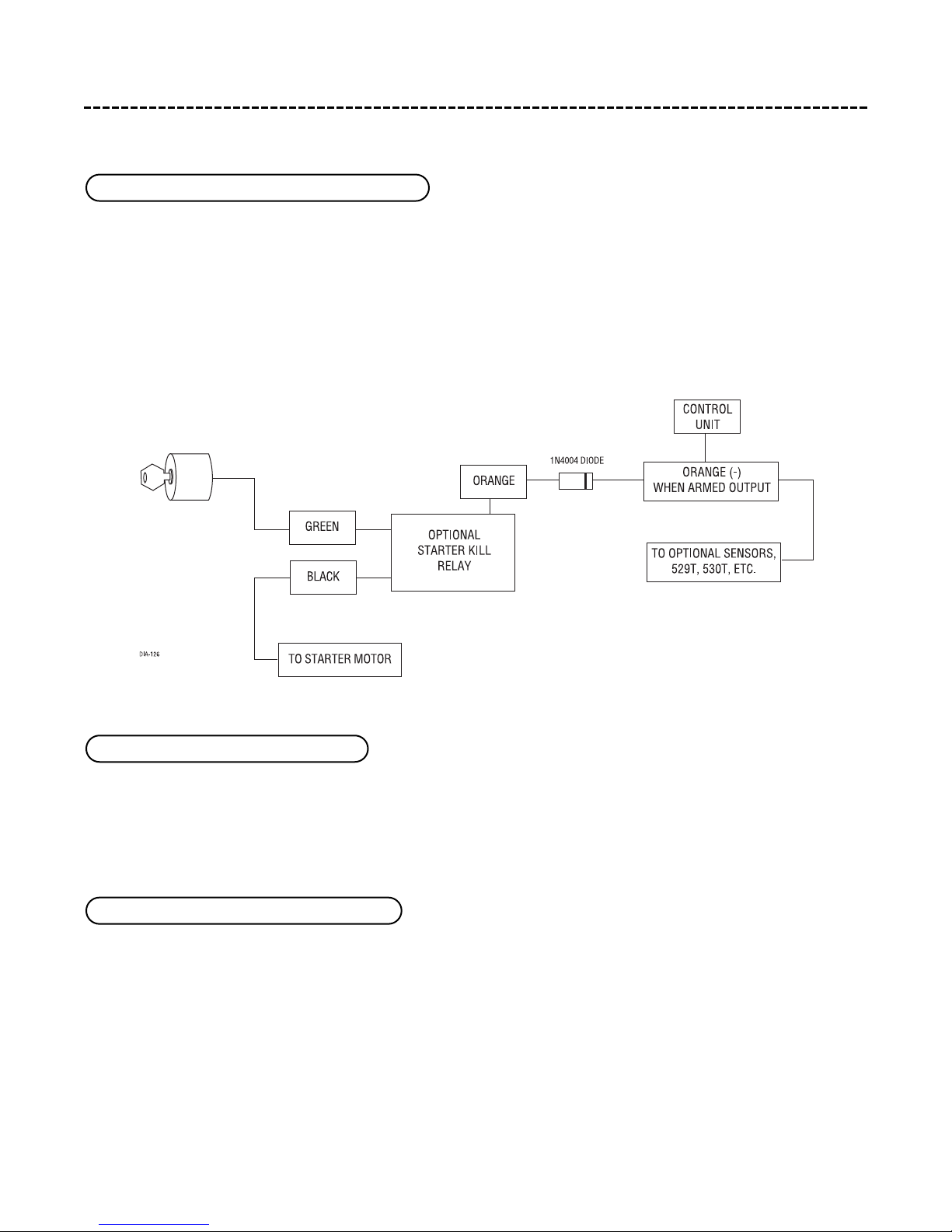
This wire supplies a (-) 500 mA output as long as the system is armed. This output ceases as soon as the system
is disarmed. The orange wire is used to control the optional starter kill relay.
NOTE: If connecting the orange wire to control another module, such as a 529T or 530T window
controller, a 1 amp diode (type 1N4004) will be required. Insert the diode as shown below.
IMPORTANT! Never interrupt any wire other than the starter wire.
This wire provides a (-) 200mA output to flash the parking lights. This is suitable for driving (-) light control
wires in Toyota, Lexus, BMW, some Mitsubishi, some Mazda, etc. If the vehicle has a positive parking light circuit,
a relay must be used to flash the parking lights.
This wire provides a (-) 200 mA output whenever the transmitter code controlling Channel 3 is received. This
output will continue as long as that transmission is received. Use for options such as DEI’s 551T Valet®Start
system, 529T or 530T power window controllers, etc.
IMPORTANT! Never use this wire to drive anything except a relay or a low-current input! The tran-
sistorized output can only provide 200 mA of current, and connecting directly to a solenoid, motor,
or other high-current device will cause it to fail.
H1/3 WHITE/BLUE (-) channel 3 output
H1/2 WHITE (-) parking light output
H1/1 ORANGE (-) ground-when-armed output

© 1999 Directed Electronics, Inc. Vista, CA 7
Connect this wire to the optional domelight supervision relay as shown below:
IMPORTANT! This output is only intended to drive a relay. It cannot be connected directly to the
domelight circuit, as the output cannot support the current draw of one or more light bulbs.
The H1/6 BLUE output is used for progressive unlock. A progressive unlock system unlocks the driver's door when
the unlock (disarm) button is pressed and unlocks the passenger doors if the unlock (disarm) button is pressed
again within 15 seconds after unlocking the driver's door. The BLUE wire outputs a low current (-) pulse on the
second press of the unlock button of the transmitter. This negative unlock output is used to unlock the passen-
ger doors.
H1/6 BLUE (-) 200 mA second unlock output
H1/4 BLACK/WHITE (-) 200 mA domelight supervision output

8© 1999 Directed Electronics, Inc. Vista, CA
Type A (+) polarity system: Wire relays as shown.
Type B (-) polarity system: Connect the BLUE H1/6 wire to the unlock wire in the vehicle and wire the relay as shown.

© 1999 Directed Electronics, Inc. Vista, CA 9
Type C (+) reversing polarity system: Wire relays as shown.
Connect this wire to bare metal, preferably with a factory bolt rather than your own screw (screws tend to either
strip or loosen with time). We recommend grounding all your components to the same point in the vehicle.
H1/8 BLACK (-) chassis ground connection

10 © 1999 Directed Electronics, Inc. Vista, CA
Connect this wire to an ignition source. This input must show (+)12V with the key in run position and during
cranking. Make sure that this wire cannot be shorted to the chassis at any point. This wire will trigger the system
if the ignition is turned on before the unit is disarmed (doors unlocked with the remote). It will also honk the
vehicle’s horn and flash the parking lights (if connected).
This wire supplies a 200 mA (-) output that can be used to honk the vehicle horn. It outputs a single pulse when
locking the doors with the remote, and two pulses when unlocking with the remote. This wire will also output
pulses for 30 seconds when the Panic Mode is activated. If the vehicle has a (+) horn circuit, an outboard relay
can be used to interface with the system, as shown below.
Before connecting this wire, remove the supplied fuse. Connect to the positive battery terminal or the constant
12V supply to the ignition switch.
NOTE: Always use a fuse within 12 inches of the point you obtain (+)12V power. Do not use the
15A fuse in the harness for this purpose. This fuse protects the module itself.
H1/11 RED (+)12V constant power input
H1/10 BROWN (-) horn honk output
H1/9 YELLOW (+) ignition input
Table of contents
Other Valet Car Alarm manuals


Popular Car Alarm manuals by other brands


Federal Signal Corporation
Federal Signal Corporation Pathfinder Siren Series Installation and maintenance manual

Falcon
Falcon Predator XL3 Installer manual

Audiovox
Audiovox Auto Security XR91 Programming guide

Clifford
Clifford Sabre II owner's manual

CrimeStopper
CrimeStopper CS-8717 Wiring diagram

Ultra Start
Ultra Start 450 SERIES install guide


