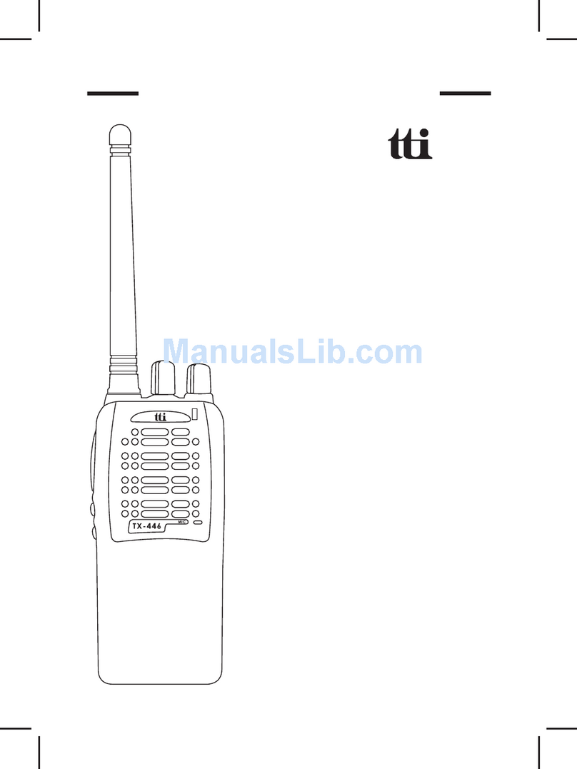
TTI PMR-1000TX User manual

Instruction Manual
Tech
Private Mobile Radio (PMR)446MHz
Model:PMR-1000TX

CAUTION
NEVER ATTEMPT TO CHARGE ALKALINE OR DRY CELL
BATTERIES. WHEN RECHARGING, USE ONLY THE RE-
CHARGEABLE BATTERIES SUPPLIED WITH YOUR TRANS-
CEIVER (OPTIONAL IN SOME CASES). USE OF OTHER
BATTERIES WILL CAUSE DAMAGE TO YOUR PMR-1000TX
TRANSCEIVER. OTHER TYPES OF BATTERIES MAY BURST
CAUSING PERSONAL INJURY.
AVOIDINSTALLINGTHEPMR-1000TX TRANSCEIVERINAN
AREA WHERE IT MAY BE SUBJECTED FOR PROLONGED
PERIODS OF TIME TO DIRECT SUNLIGHT OR TEMPERA-
TURES BELOW -4°F (-20°C) OR ABOVE 140°F (60°C).
KEEP THE ANTENNA AT LEAST 1 INCH (2.5 cm) AWAY
FROM YOUR HEAD AND BODY. DO NOT USE YOUR
PMR-1000TX RADIO TRANSCEIVER WITH A DAMAGED
ANTENNA.

Model PMR-1000TX
1. Battery CHARGE On/Off Switch
2. Liquid Crystal Display (LCD)
3. TX/RX LED
4. Antenna
5. Battery Door
6. Voice-Operated Transmission
(VOX) Button
7. Monitor Button
8. SCAN/Lock Button
9. Built-in Speaker
10. Built-in Microphone
11. CALL Button
12. DC12V Power Jack
13. Charging (CHG.) LED (Red)
14. Up/DownChannel/
VolumeButtons
15. Memory 1 Button
16. MODE Button
17. Memory 2 Button
18. Power On/Off Button
19. External Speaker(SPK)/
Microphone (MIC) Jacks
20. Push-To-Talk (PTT) Button
14
17
19
20
16
18
15
13
12
6
8
5
4
10
11
2
9
7
1
3
SPK MIC
DC12V CHARGE
OFF ON
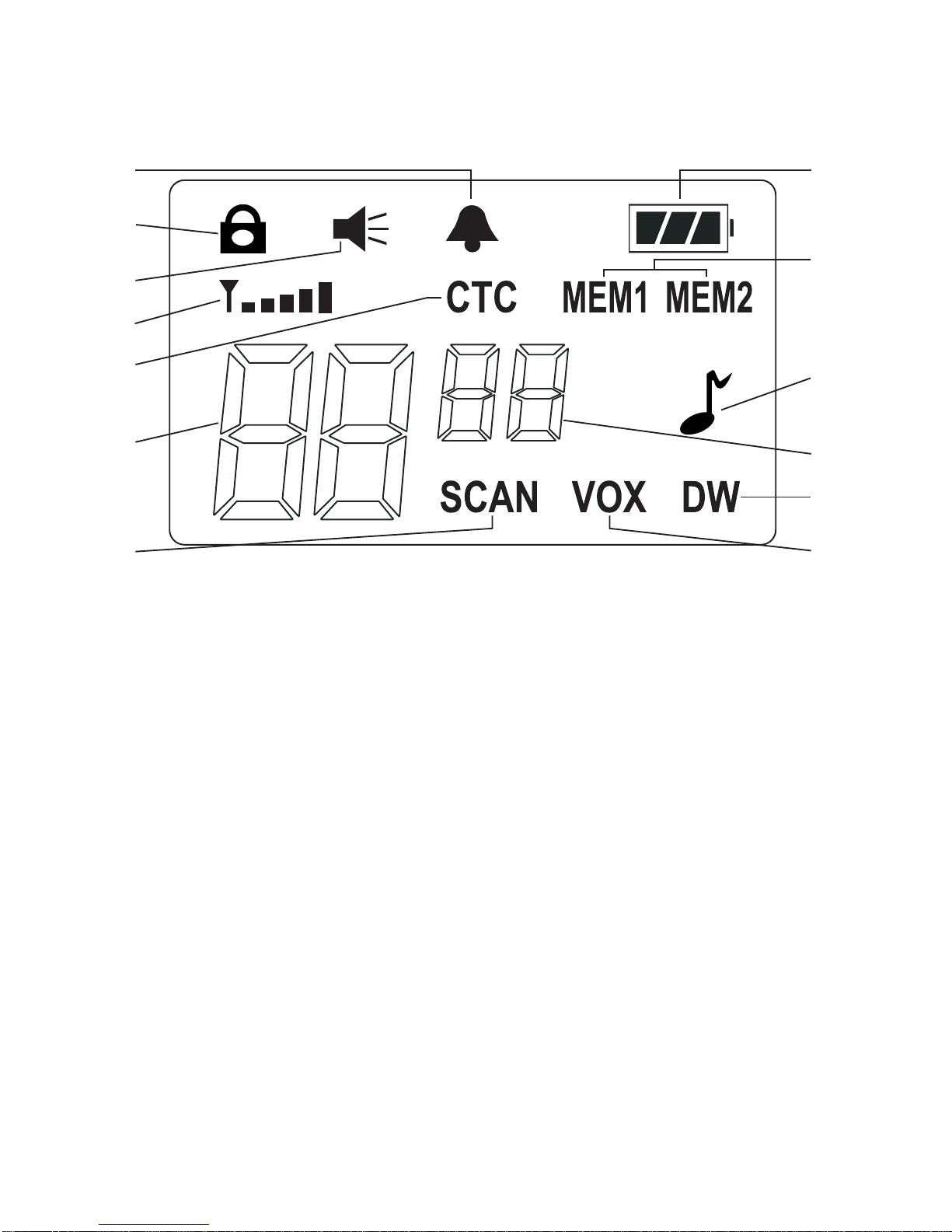
Model PMR-1000TX DISPLAY
1. Beep On/Off Indicator: This icon appears when the beep key
tone is on, and disappears when tone is not in use.
2. Key Lock Indicator: Icon appears when keypad is locked. This
function disables keys such as MODE, Memory, SCAN and VOX.
3. Monitor Indicator: Icon appears when the Monitor (MON) button
is pressed and the channel monitor function is activated.
4. Signal Strength Indicator: Icon appears when a signal is being
received. The icon consists of five bars to indicate the received
signal level.
5. Continuous Tone Coded Squelch System (CTCSS) Indicator:
Icon appears when the CTCSS tone function is active.
6. Large Segment Display: Indicates the PMR-446 Radio channel
number in use.
7. Scan Indicator: This function allows the user to scan a channel
to search for a valid signal.
8. Battery Level Indicator: Icon indicates the battery charge level.
9. MEM1 / MEM2 Indicators: Appropriate icon appears when the
required memorized channel is selected.
11
10
12
13
7
8
6
4
5
3
2
1
9

Powering the transceiver:
The primary power source for Your PMR-1000TX base station is the
AC wall adaptor. The PMR-1000TX is also supplied with a battery
back-up, should you experience loss of household current.
The PMR-1000TX will automatically switch to battery back-up when AC
power is interrupted.
The rechargeable batteries are charged in the radio transceiver using
the AC power adaptor, which is also supplied with the unit.
Installing the Back-Up Batteries
(For some customers, batteries are optional.) :
The four AA batteries are installed in the compartment at the right
rear of the transceiver; the compartment is fitted with a removable
cover. Install the batteries as follows:
1. Press down with the thumb at the arrow, and slide the battery cover
off the side of the unit.
2. Insert the four AA rechargeable batteries provided. (Alternate
positive ends (+) as shown in battery compartment layout.) Replace
the cover.
10. Roger Beep Tone Indicator: Icon appears when the roger beep
tone is enabled, signifying transmission has been terminated.
Icon disappears when tone is disabled.
11. Small Segment Display: Displays the CTCSS tone option for a
given channel from (01-38).
12. Dual Watch Mode Indicator: Icon appears when dual watch
mode is active.
13. Voice Activated Transmission (VOX) Indicator: This
function allows hands-free conversation. The icon appears
when the VOX mode is activated.

The following guidelines will improve performance and provide
longer operating times for the PMR-1000TX:
BATTERY
INSTALLATION
POLARITY
BATTERY
COMPARTMENT
COVER
BATTERY
COMPARTMENT
COVER ARROW
1. Do not mix old and new batteries.
2. Do not mix alkaline, or rechargeable (Ni-MH) batteries.
3. If the unit is not to be used for an extended period of time,
remove the batteries. Old or leaking batteries can cause
damage to the unit and will void the warranty.
Charging The Rechargeable Batteries:
The rechargeable batteries, supplied with the unit, are
charged by connecting the AC Adaptor plug to the DC12V
jack on the top of the unit, and setting the CHARGE switch
to the ON position. Use only the AC Wall Adaptor that is
supplied with the base unit. The CHG. LED indicator below
the LCD display lights
red
during battery charge operation.

The battery charge indicator icon displays the battery charge level
when the AC adaptor is unplugged. When the AC adaptor is connected
and in use, the indicator icon will indicate a full charge as shown below.
Full Battery - three segments are illuminated.
Low Battery - one segment is illuminated.
Approximately 20–24 hours are required to fully charge the batteries.
The red LED charging indicator (12) will light whenever the batteries
are charging. A flashing red LED-charging indicator denotes batteries
are not installed. You must set the CHARGE switch to the OFF
position, when using any batteries other than the ones provided.
Failure to do this may cause damage to batteries resulting in personal
injury and/or damage to the unit.
Caution: The charging adaptor is intended for use with the supplied
rechargeable Ni-MH batteries. Do not attempt to recharge
any other type batteries.
CHARGE
ON/OFF
SWITCH ADAPTOR
PLUG
AC
ADAPTOR
DC12V
JACK BASE
UNIT
DC12V CHARGE
OFF ON

PMR-1000TX OPERATIONAL MODES
CHANNEL
SELECT
CALL
SELECT
MODE
CTCSS
SELECT
DUAL
WATCH
ROGER
BEEP
BEEP TONE
MEMORY1
SELECT
MEMORY2
SELECT

Controls:
Power On/Off (18) Button
Press and hold the power on/off button ( ) for at least 2 seconds.
You will hear a confirming melody to indicate the unit is on. To turn
the unit off, press and hold the button for at least 2 seconds.
Adjusting the Volume
With the unit powered on, press the Up Channel/Volume button
( ) to increase volume and the Down Channel/Volume button ( )
to decrease volume. The display will indicate the current volume level
by the small number adjacent to the icon ( )
This button is used to check activity on the current frequency before
transmitting. Check activity by pressing the Monitor (MON) button
longer than 2 seconds; the icon will appear on the display
and you will hear static if frequency is clear.
Donottransmitifyouhear conversation.
HolddowntheMONbuttonagain
longer than 2 seconds and the icon will disappear from the
display. The monitor function will temporarily bypass the squelch setting
and play all signals on a given channel. This feature is useful when
communicating with other parties at extreme range. By pressing the
monitor button momentarily, the LCD backlight is turned on; the LCD
backlight will turn off automatically in about 5 seconds, or when the
MON button is pressed momentarily once again.
Push To Talk (PTT) Button (20)
Pressing and holding this button will allow you to speak to any transceiver
that is set to the same channel and privacy code setting as yours.
Afteryou havefinishedspeaking,releasethePTTbuttontoallow reception
of incoming signals. It is not possible to transmit and receive at the
same time. The Transmit (TX) LED at the upper left side of the LCD
panel will light
red
while the PTT button is pressed. Releasing the button
allows the unit to revert to standby mode. When receiving an incoming
signal, the received signal strength indicator ( ) will display
the relative strength of the signal, and the receive (RX) LED at the
lower left side of the LCD will light green.
Monitor/(MON)Button(6)

CALLButton(11)
Pressing the button will call another party on the same channel.
The Transmit LED will light
red
for approximately 3 seconds and
then go out.
Up Channel/Volume Button (14)
In the standby mode, pressing this button ( ) will increment
the listening volume. When in function edit mode, this button will
be used to adjust the unit’s settings.
Down Channel/Volume Button (14)
In the standby mode, pressing this button ( ) will decrement the
listening volume. When in function edit mode, this button will be
used to adjust the unit’s settings.
Mode Button (16)
In the standby mode, pressing this button momentarily will enter
the function edit mode. Subsequent presses will cycle to each mode.
The MODE button is used to select various features for adjustment.
External Speaker (SPK)/Microphone (MIC) Jacks (19)
Thisset ofjacks acceptsan externalheadset/microphone connector.
Referto the Operational Modes.
Scan/Lock Mode Button (8)
Press this button momentarily to enable or disable the scan mode.
Press and hold button for more than 1 second to lock or unlock keypad
functions, except PTT, Call, Monitor (MON), Power on/off and Volume
up/down. When the keypad is locked, the ( ) icon will appear
in the upper left corner of the display.
Operational modes
Channel Selection
In order to communicate with other PMR-446 units, both transmitting
and receiving party must be on the same frequency. The PMR-1000TX
has 8 channels (frequencies 01-08) indicated by the large digits on
the LCD display panel. Communication with any compatible units
is possible on these 8 channels. Before transmitting on the selected
Table of contents
Other TTI Radio manuals