Toyama SmartGen HGM400N Series User manual

PLEASE READ THIS MANUAL CAREFULLY. IT CONTAINS INFORMATION FOR YOUR SAFETY.
POR FAVOR, LEA ATENTAMENTE ESTE MANUAL. CONTIENE INFORMACIÓN PARA SU SEGURIDAD.
POR FAVOR, LEIA ATENTAMENTE ESTE MANUAL. ELE CONTÉM INFORMAÇÕES PARA SUA SEGURANÇA.
OWNER’S MANUAL
GUÍA DEL PROPIETARIO • MANUAL DO PROPRIETÁRIO
Controller Manual
Manual del Controlador •manual do controlador


English
PERFORMANCE AND CHARACTERISTICS _______________________________04
SPECIFICATION ______________________________________________04
OPERATION ________________________________________________05
PUSHBUTTONS ______________________________________________05
NDICATOR LIGHT _____________________________________________06
DEFINITION AND RANGE OF PARAMETERS_______________________________07
PARAMETERS SETTINGS _________________________________________12
TYPICAL APPLICATION __________________________________________13
OVERALL DIMENSION AND PANEL CUTOUT ______________________________14
Español
RENDIMIENTO Y CARACTERÍSTICAS __________________________________16
ESPECIFICACIONES ____________________________________________16
FUNCIONAMIENTO_____________________________________________17
Botones ___________________________________________________17
INDICADORES _______________________________________________18
DEFINICIÓN Y RANGO DE PARÁMETROS ________________________________19
CONFIGURACIÓN DE PARÁMETROS __________________________________25
TYPICAL APPLICATION __________________________________________26
DIMENSIÓN GENERAL Y CORTE DEL PANEL ______________________________28
Português
DESEMPENHO E CARACTERISTICAS __________________________________30
ESPECIFICAÇÕES _____________________________________________30
OPERAÇÃO_________________________________________________31
BOTÕES __________________________________________________31
INDICADORES _______________________________________________32
DEFINIÇÃO E FAIXA DE PARAMETROS _________________________________33
CONFIGURAÇÃO DE PARAMETROS ___________________________________39
APLICAÇÃO TIPICA ____________________________________________40
DIMENSÃO GERAL E CORTE DO PAINEL ________________________________42
INDEX / INDICE / SUMÁRIO

HGM410N/HGM420N GENSET
CONTROLLER USER MANUAL
4
HGM400N series controller has two types:
HGM410N: ASM (Automatic Start Module), it controls generator to start/stop by remote signal;
HGM420N: AMF (Auto Mains Failure), updates based on HGM410N, moreover, has mains electric quantity monitoring and mains/genera-
tor automatic transfer control function, especially for automatic system composed by generator and mains.
Items Contents
Working Voltage DC8. 0V to 35. 0V, Continuous Power Supply.
Overall Consumption <3W(Standby mode: ≤2W)
AC voltage Input:
3 Phase 4 Wire
3 Phase 3 Wire
Single phase 2 Wire
2 Phase 3 Wire
AC15V - AC360V (ph-N)
AC30V - AC620V (ph-ph)
AC15V - AC360V (ph-N)
AC15V - AC360V (ph-N)
Alternator Frequency 50Hz/60 Hz
Speed Sensor Voltage 1.0V to 24V (RMS)
Speed Sensor Frequency 10,000 Hz (max)
Start Relay Output 5A DC28V power supply
Auxiliary Relay Output 1 5A DC28V power supply
Auxiliary Relay Output 2 5A DC28V power supply
Auxiliary Relay Output 3 5A DC28V power supply
Auxiliary Relay Output 4 5A AC250V voltage-free output
Auxiliary Relay Output 5 5A AC250V voltage-free output
Overall Dimensions 126mm x 109mm x 44mm
Panel Cutout 110mm x 90mm
CT Secondary Current 5A (rated)
Working Condition Temperature: (-25~70)ºC;
Humidity: (20~90)%RH
Storage Condition Temperature: (-30~+80)ºC
Protection Level IP55 Gasket
Insulation Intensity Object: among input/output/power supply
Quoted standard: IEC688-1992
Test method: AC2.2kV/1min Ileak≤3mA
Weight 0.26kg
2. SPECIFICATION
1. PERFORMANCE AND CHARACTERISTICS
HGM410N/HGM420N GENSET
CONTROLLER USER MANUAL
5
3. OPERATION
3.1 PUSHBUTTONS
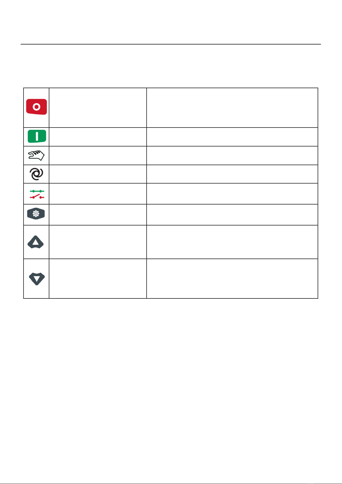
Stop/ Reset
Stop running generator in Auto/Manual mode;
In case of alarm condition, pressing the button will reset alarm;
In stop mode, pressing and holding the button for 3 seconds will
test indicator lights (lamp test);
During stopping process, press this button again to stop generator
immediately.
Start Start genset in Manual/Test mode. When press this key in starting
process, genset will skip to next status.
Manual Pressing this key will set the module into manual mode.
Auto Pressing this key will set the module into auto mode.
Close/Open
For close/open switch. Pressing this key can switch between
close/open interface and homepage. At close/open interface in
manual mode, pressing up/down keys can control open or close.
Set/ Conrm
Pressing this key will enter into Main Menu;
In setting parameter status, press this key will shift cursor or con-
rm setting value.
Up/Increase
Scrolls the screen up; shift the cursor up or increase the set value
in parameter setting menu.
When at close/open interface in manual mode:
Pressing this key can control mains close/open (HGM420N) and
gen close (HGM410N).
Down/Decrease
Scrolls the screen down; shift the cursor down or decrease the set
value in parameter setting menu.
When in close/open interface in manual mode:
Pressing this key can control mains close/open (HGM420N) and
gen close (HGM410N).
HGM410N/HGM420N GENSET
CONTROLLER USER MANUAL
6
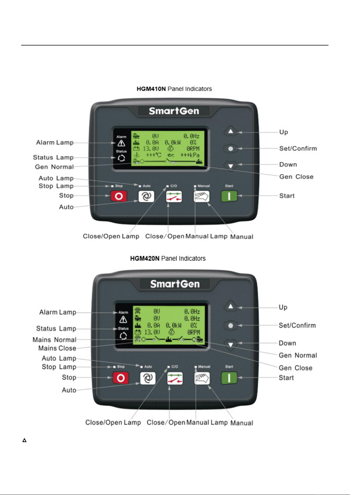
Note:Note: Partial indicator states
Alarm Lamp: slowly blink when warning alarms; fast blink when shutdown alarms; won’t illuminate when there is no alarm.
Status Lamp: won’t illuminate when genset stand by; blink 1 time in start or stop process and always illuminate when runs normally.
3.2 INDICATOR LIGHT
HGM410N/HGM420N GENSET
CONTROLLER USER MANUAL
7
4.DEFINITION AND RANGE OF PARAMETERS
No. Items Range Default Description
1 Mains Normal Delay (0-3600)s 10 The time from mains abnormal to normal or
from normal to abnormal; suitable for ATS (auto-
matic transfer switch).
2Mains Abnormal
Delay (0-3600)s 5
3 Mains Under Volt (30-620)V 184
When mains voltage has fallen below the set value,
Mains Under Voltage is active. When set the value
as 30V, the controller does not detect under volta-
ge signal. Back lash: 10V
4 Mains Over Volt (30-620)V 276
When mains voltage has exceeded the set value,
Mains Over Voltage is active. When set the value
as 620V, the controller does not detect over volta-
ge signal. Back lash: 10V
5 Transfer Rest Delay (0-99.9)s 1.0
Interval time from mains switch o to generator
switch on; or from generator switch o to mains
switch on.
6 Start Delay (0-3600)s 1 Time from mains abnormal or remote start signal
is active to start genset.
7 Stop Delay (0-3600)s 1 Time from mains normal or remote start signal is
deactivated to genset stop.
8 Start Attempts (1-10)times 3
Maximum crank times of crank attempts. When
reach this number, controller will send start failure
signal.
9 Preheat Time (0-300)s 0 Power-on time of heater plug before starter is
powered up.
10 Cranking Time (3-60)s 8 Power-on time of starter
11 Crank Rest Time (3-60)s 10 The waiting time before second power up when
engine start fail.
12 Safety On Delay (1-60)s 10
Alarms for low oil pressure, high temperature,
under speed, under frequency/voltage, charge alt
failure are inactive.
13 Start Idle Time (0-3600)s 0 Idle running time of genset when starting.
14 Warming Up Time (0-3600)s 10 Warming time between genset switch on and high
speed running.
15 Cooling Time (3-3600)s 10 Radiating time before genset stop, after it unloads.
16 Stop Idle (0-3600)s 0 Idle running time when genset stop.
17 ETS Solenoid Hold (0-120)s 20 Stop electromagnet’s power on time when genset
is stopping.
18 Fail to Stop Delay (0-120)s 0
Time between ending of genset idle delay and
stopped when “ETS time” is set as 0;
Time between ending of ETS hold delay and
stopped when “ETS time” is not 0.
19 Breaker Close Time (0-10)s 5.0 Pulse width of mains/generator switch on. When it
is 0, means output constantly.
20 Flywheel Teeth (10-300) 118
Tooth number of the engine, for judging of starter
crank disconnect conditions and inspecting of
engine speed. See the installation instructions.
21 Gen Abnormal Delay (0-20.0)s 10.0 The alarm delay of generator over voltage and
under voltage.
22 Gen Over Volt (30-620)V 276
When generator voltage has exceeded the set
value and the “Gen abnormal delay” has expired,
Gen Over Voltage is active. When set the value as
620V, the controller does not detect over voltage
signal.
HGM410N/HGM420N GENSET
CONTROLLER USER MANUAL
8
23 Gen Under Volt (30-620)V 184
When generator voltage has fallen below the set
value and the “Gen abnormal delay” has expired,
Gen Under Voltage is active. When set the value as
30V, the controller does not detect under voltage
signal.
24 Under Speed (0-6000)r/min 1200
When engine speed has fallen below the set value
for 10s, Under Speed is active. It will initiate a shut-
down alarm signal.
25 Over Speed (0-6000)r/min 1710
When engine speed has exceeded the set value for
2s, Over Speed is active. It will initiate a shutdown
alarm signal.
26 Under Freq (0-75.0)Hz 40.0
When generator frequency has fallen below the set
value but Not equal to 0 for 10s, Under Frequency
is active. It will initiate a shutdown alarm signal.
27 Over Freq (0-75.0)Hz 57.0
When generator frequency has exceeded the set
value for 2s, Over Frequency is active. It will initia-
te a shutdown alarm signal.
28 High Temp. (80-140)ºC 98
When the temperature value of the external
temperature sensor exceeds the set value, “High
Temperature” timer is initiated. Detecting only after
safety on delay has expired. If the set value is 140,
high temperature signal will not be sent (this only
concerns external temperature sensor, not high
temperature signal via cong. input port).
29 Low OP (0-400)kPa 103
When the external pressure sensor value falls
below this set value, “Low Oil Pressure” timer is
initiated. Detecting only after safety on delay has
expired. If the set value is 0, low oil pressure signal
will not be sent (this only concerns pressure sen-
sor and does not concern low oil pressure warning
signal via congurable input port)
30 Low Fuel Level (0-100)% 10
When the liquid level of the external sensor falls
below the set value, “Low Fuel Level” timer is
initiated. (this only concerns fuel level sensor and
does not concern low fuel level warning signal via
congurable input port)
31 Aux. Sensor (80-140)ºC (0-400)kPa
(0-100)% 98
Each value correspond to above 28 (Temperature
sensor), 29 (Oil pressure sensor) and 30 (Level
sensor), respectively.
32 Loss of Speed Signal (0-20.0)s 5.0 If the set value is 0, only warning and not to shut-
down the generator.
33 Charge Alt Failure (0-30)V 6.0
During generator is normal running, when alterna-
tor D+(WL) voltage has fallen below the set value
and remains for 5s, It will initiate a shutdown alarm
signal.
34 Battery Over Volt (12-40)V 33.0
When battery voltage has exceeds the set value
and remains for 20s, It will initiate a warning alarm
signal. Only warning and not to shutdown the
generator.
35 Battery Under Volt (4-30)V 8.0
When battery voltage has fallen below the set
value and remains for 20s, It will initiate a warning
alarm signal. Only warning and not to shutdown
the generator.
36 Current Trans. (5-6000)/5 500 The ratio of external CT
37 Full Load Current
Rating (5-6000)A 500 Generator’s rated current, used for load over cur-
rent calculating.
38 Over Current Percen-
tage (50-130)% 120 When the load current has exceeded the set value,
“over current” delay is initiated.
HGM410N/HGM420N GENSET
CONTROLLER USER MANUAL
9
39 Over Current Delay (0-3600)s 30
When load current has exceeded the set value and
the “over current” delay has expired, over current
alarm is initiated. When the set value is 0, only
warning and not to shutdown the generator.
40 Fuel Pump On (0-100)% 25 When fuel level has fallen below the set value for
10s, “Fuel Pump On” alarm is initiated.
41 Fuel Pump O (0-100)% 80 When fuel level has exceeded the set value for 10s,
“Fuel Pump O” alarm is initiated.
42 Aux. Output 1 (0-17) 14 Factory default: Fuel Relay Output
43 Aux. Output 2 (0-17) 2 Factory default: Energized To Stop
43 Aux. Output 3 (0-17) 5 Factory default: Gens closed
44 Aux. Output 3 (0-17) 3 Factory default: Idle Control
45 Aux. Output 4 (0-17) 5 Factory default: Close Generator
46 Aux. Output 5 (0-17) 6 Factory default: Mains Closed
47 Digital Input 1 (0-15) 1 Factory default: High Temperature Input
48 Digital Input 1 Active (0-1) 0 Factory default: Close to active
49 Digital Input 1 Delay (0-20.0)s 2.0
50 Digital Input 2 (0-15) 2 Factory default: Low Oil Pressure Warning Input
51 Digital Input 2 Active (0-1) 0 Factory default: Close to active
52 Digital Input 2 Delay (0-20.0)s 2.0 Factory default: close
53 Digital Input 3 (0-15) 10 Factory default: Remote Start
54 Digital Input 3 Active (0-1) 0 Factory default: Close to active
55 Digital Input 3 Delay (0-20.0)s 2.0 Factory default: close
56 Digital Input 4 (0-15) 11 Factory default: Fuel Level Warn
57 Digital Input 4 Active (0-1) 0 Factory default: Close to active
58 Digital Input 4 Delay (0-20.0)s 2.0 Factory default: close
59 Power On Mode (0-2) 0 0: Stop Mode 1: Manual Mode 2: Auto Mode
60 Module Address (1-254) 1 Communication address of controller.
61 Passwords (0-9999) 0318
62 Crank Disconnect (0-6) 2
There are 3 conditions of disconnecting starter
with engine: Generator Frequency, Magnetic
Pickup, Oil Pressure. Each condition can be used
alone and simultaneously to separating the start
motor and genset as soon as possible. See 7.5
63 Disconnect Magnetic
Pickup (0-3000)r/min 360 When engine speed higher than the set value, star-
ter will be disconnected.
63 Disconnect Magnetic
Pickup (0-3000)r/min 360 When engine speed higher than the set value, star-
ter will be disconnected.
64 Disconnect Gen Freq (10.0-30.0)Hz 14.0 When generator frequency higher than the set
va-lue, starter will be disconnected.
65 Disconnect OP (0-400)kPa 200 When generator oil pressure higher than the set
value, starter will be disconnected.
66 High Temp. Inhibit
Enabled (0-1) 0 Factory default: when high temperature occurs,
shutdown alarm is initiated. Note 2
67 Low OP Inhibit Ena-
-bled (0-1) 0 Factory default: when low oil pressure occurs,
shu-tdown alarm is initiated. Note 3
68 Low Fuel Level
Inhibit (0-1) 1 Factory default: when low fuel level occurs, shu-t-
down alarm is initiated. Note 4
69 Cong. Sensor
Inhibit (0-1) 1
Factory default: when cong. sensor value higher/
lower than the set value (particular case depends
on the sensor type), shutdown alarm is initiated.
70 AC System (0-3) 0 0: 3P4W; 1: 2P3W 2: 1P2W; 3: 3P3W
71 Temp. Sensor Curve (0-12) 8 SGX See 7.4
HGM410N/HGM420N GENSET
CONTROLLER USER MANUAL
10
72 Pressure Sensor
Curve (0-12) 8 SGX See 7.4
73 Multiplex Input 1 (0-1) 0 0: Digital Input 3
1: Level Sensor
74 Level Sensor Curve (0-7) 3 SGD See 7.4
75 Multiplex Input 2 (0-3) 0 0: Digital Input 4 1: Temperature Sensor 2: Oil
Pressure Sensor 3: Level Sensor Note 5
76 Cong. Sensor Curve (0-9) (0-9) (0-5) 8 8 3 SGX SGX SGD
77 Poles (2-64) 4
0:Dened temperature sensor
1: Dened pressure sensor
2: Dened liquid level sensor
Select the sensor, input corresponding 8 values.
78 Temp. Sensor Open (0-2) 1 0:Indication; 1:Warn; 2:Shutdown (temperature
sensor will show “+++”);
79 OP Sensor Open (0-2) 1 0: Indication (oil pressure sensor will show “+++”);
1:Warn; 2:Shutdown
80 Fuel Level Sen-sor
Open (0-2) 1 0: Indication (fuel level sensor will show “+++”);
1:Warn; 2:Shutdown
81 Cong. Sensor Open (0-2) 1 0: Indication (LCD display will show “+++”);
1:Warn; 2:Shutdown
82 Cooling Blower On (0-140)ºC 60 It controls the cooling blower to open or close if
the output port is congured as Cooling Blower.
83 Cooling Blower O (0-140)ºC 40
84 Low Fuel Level Warn (0-100)% 20
When the liquid level of the exter-nal sensor falls
below the set value, “Low Fuel Level” timer is
initiated. (this only concerns fuel level sensor and
does not concern low fuel level warning signal via
congurable input port)
85 Gen Over Volt Warn (30-620)V 253
When genset voltage is over the point, genera-tor
over voltage is active. When the point is 620V,
generator over voltage is disa-bled.
86 Gen Under Volt (30-620)V 193
When generator voltage is under the point, genera-
-tor under voltage is active. When the point is 30V,
generator under voltage is disabled.
87 Gen Over Freq Warn (0-75.0)Hz 55.0 When generator’s frequency is over the point,
genera-tor over frequen-cy is active.
88 Gen Under Freq
Warn (0-75.0)Hz 42.0 When generator frequency is lo-wer than the point,
warn alarm signal will be sent.
89 Gen Over Current
Warn (50-130)% 110
When load cur-rent is over the point, over current
is active. When this value is 0, warn alarm signal
won’t be sent.
90 High Temp. Warn (80-140)ºC 95
When the tempe-rature value of the external
tem-perature sensor exceeds the set value, “High
Temperature” timer is initiated. Detecting only after
safety on delay has expired. If the set value is 140,
high tempe-rature signal will not be sent (this only
concerns external tempera-ture sensor, not high
temperature signal via cong. input port).
91 Low OP Warn (0-400)kPa 124
When the exter-nal pressure sen-sor value falls
below this set value, “Low Oil Pressure” timer
is initiated. Detec-ting only after safety on delay
has expired. If the set value is 0, low oil pressure
signal will not be sent (this only con-cerns pressu-
re sensor and does not concern low oil pressure
war-ning signal via congurable input port)
92 Aux. Sensor Warn (80-140)ºC (0-400)kPa
(0-100)% 95
Respective cor-responding with 90 temp. sensor,
91 pressure sen-sor and 84 level sensor in this
table.
This manual suits for next models
2
Table of contents
Languages:
Popular Controllers manuals by other brands

Digiplex
Digiplex DGP-848 Programming guide

YASKAWA
YASKAWA SGM series user manual

Sinope
Sinope Calypso RM3500ZB installation guide

Isimet
Isimet DLA Series Style 2 Installation, Operations, Start-up and Maintenance Instructions

LSIS
LSIS sv-ip5a user manual

Rockwell Automation
Rockwell Automation 1769-L31 installation instructions


