
Tough Jets T-15 EDF User manual

©2013 ToughJets, LLC Kittery, ME Page 1 of 22
Wingspan……………….31in Weight……………..2.5 lb
Length…………………..41.75in Radio………...3 channel
Wing Area………………515 sq in Motor………...Brushless
EDF............70mm 12 Blade Battery…14.8v 2200mah 40c
T-15 EDF
INSTRUCTION MANUAL
Specifications
T
M

©2013 ToughJets, LLC Kittery, ME Page 2 of 22
KIT CONTENTS
(1) Wing
(1) Fuselage
(2) Nacelles
(1) Battery box spacer
(2) Vertical stabilizers
(1) Canopy
(1) Canopy hinge
(2) 14 Gauge wire
(2)3mm X 14mm Bolts
(2)3mm Lock Nuts
(2)Flat washers
(4) Control horns
(4) Clevis
(2) Push rods
(2) Push rod keepers
(2)Coroplast® motor mount stiffener
(4) Wood dowels
(1) Carbon fiber shaft 30 inch (1) Carbon Fiber shaft 25 inch
(1) Rare Earth magnets

©2013 ToughJets, LLC Kittery, ME Page 3 of 22
BEFORE YOU BUILD
WARNING!!
This kit is not a toy.
This model is intended for the competent builder and RC pilot aged 14
years and older. It is the responsibility of the modeler to ensure the
model is airworthy before attempting to fly it.
Always ensure that any glue, paint or solvents used to build this kit are compatible with the
materials contained in this kit. Some glues and paint can melt Styrofoam and plastic that is
contained in this kit.
Before gluing any parts together, we strongly suggest trial fitting the parts without glue first;
to ensure that all the parts align and fit properly. This will ensure the airplane is built straight
and square.
ABOUT THE TOUGH JETS T-15 EDF
The Tough Jets T-15 EDF was designed by life-long RC modeler Wayne Roberts to be the
highest performing fun scale Electric Ducted Fan on the market. You’ll find the T-15 has an
enormous flight envelope. It’s capable of 65+mph, it’s highly aerobatic, yet it lands at near
zero ground speed in the slightest of headwinds.
TOOLS AND SUPPLIES REQUIRED
5 Minute Epoxy
Electric Drill
Assorted Drill Bits
Needle nose pliers
Small screw drivers
Allen wrench 2.5mm
Hobby knife
Wire Cutters
Scissors
Clear Packaging Tape
Pencil
Rubbing Alcohol
©2013 ToughJets, LLC Kittery, ME Page 4 of 22
ADDITIONAL EQUIPMENT REQUIRED
3, channel radio with mixing (Minimum)
4, sub micro 9 gram servos (Tower Pro or equivalent)
2, Y servo cords.
70mm 12 blade Ducted Fan (FMS 70mm Ducted Fan or equivalent)
70 amp electronic speed control
4 cell lipo battery 14.8 volt 2200 mAh 40 c or 2600mAh 40 c
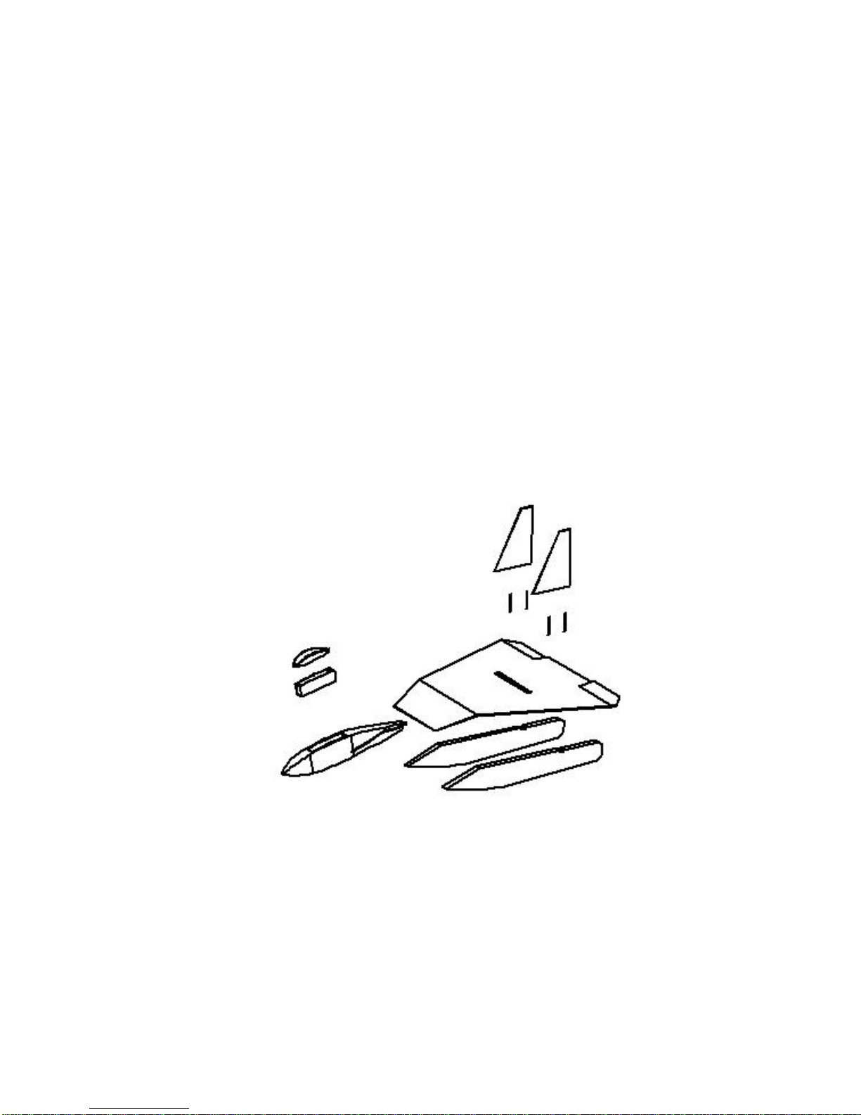
EXPLODED VIEW
Use this exploded view to help guide you through the assembly of the major components
of your Tough Jet.

©2013 ToughJets, LLC Kittery, ME Page 5 of 22
LET’S BEGIN BUILDING
It is strongly suggested you review the drawings, photos and captions to familiarize yourself
with the design and construction of the model.
Before beginning construction, you will want to decide whether to paint or cover the foam
parts with heat shrink film such as EconoKote, or packaging tape. You may also choose to
leave these parts uncovered. If you choose EconoKote, or packaging tape, spray the surfaces
to be covered with 3M Type 77 spray adhesive prior to covering. Allow the adhesive to set for
5 minutes prior to applying the covering, this will improve the overall adhesion of the covering
to the foam. When covering or painting the nacelles, do not apply covering material to the
surfaces to be epoxied to the wing.
It is recommended to apply the covering material or paint prior to assembling the
model. Do NOT apply covering to the top edge and slant of the nacelle (see insert)

©2013 ToughJets, LLC Kittery, ME Page 6 of 22
WING / NACELLE / FUSELAGE ASSEMBLY
Lay wing on a flat surface, bottom side up.
This is the side with the hinge slots and
crease.
Clean the bottom of the wing with rubbing
alcohol before gluing
Apply 5 minute epoxy to top of nacelle on
flat section only. Do not apply epoxy to
slanted section at this time.
Carefully align nacelle with leading edge and
crease on the bottom of the wing.

©2013 ToughJets, LLC Kittery, ME Page 7 of 22
Ensure the nacelle is parallel and 90 degrees
to prop slot in wing. You have some time to
make slight adjustments before epoxy cures
but move quickly.
Be sure that the nacelle is properly aligned
with crease
Hold the nacelle in place until the five-
minute epoxy cures, check that nacelle is
aligned with leading edge, crease and
centered on Vertical stabilizer dowel holes on
wing.
Repeat the steps to attach the second
nacelle to the wing. Nacelles should be
straight and parallel

©2013 ToughJets, LLC Kittery, ME Page 8 of 22
Now apply 5-minute epoxy to the slanted
sections on both nacelles. Press both nacelles to leading edge of the
wing applying pressure on a smooth flat
surface for 5 minutes until the e
p
ox
y
cures
Turn the wing over, measure and mark on
the top the center of the wing Apply 5 minute epoxy to both side of
fuselage wing slot. Slide the fuselage onto
the wing. Be sure that the fuselage is
centered straight and square to wing.

©2013 ToughJets, LLC Kittery, ME Page 9 of 22
Epoxy 2 dowels into the flutes of each
vertical stabilizers. Position the dowels 1½”
and 4 ½” from the trailing edge. Leave
about 1 ½” of dowel exposed
Twist a 1/8-inch drill bit in Vertical stabilizer
dowel holes to clear out foam to for dowels
Place Vertical stabilizer in wing at this time
you can chose to glue in place permanently
or leave loose so you can remove
for transporting model.
Repeat steps for other side. It’s starting to
look like a plane now.

Apply a little 5 minute epoxy to the 30 inch
carbon fiber shaft, then insert it in a wing
flute approximately 2, 7/8th inches behind
the EDF (see photo)
Apply a little 5 minute epoxy to the
25 inch carbon fiber shaft then insert it
in a wing flite approximately 8, 7/8th
inches behind the EDF (see photo)
Table of contents
Other Tough Jets Toy manuals






