
Toa H-1 User manual

OPERATING INSTRUCTIONS
SPEAKER SYSTEM H-1
Please follow the instructions in this manual to obtain the optimum results from this unit.
We also recommend that you keep this manual handy for future reference.
TABLE OF CONTENTS
1. SAFETY PRECAUTIONS ............................................................................................... 2
2. GENERAL DESCRIPTION ............................................................................................ 3
3. FEATURES ......................................................................................................................... 3
4. NOMENCLATURE ............................................................................................................ 4
5. INSTALLATION
5.1. Direct Wall/Ceiling Mounting Without Using an Electrical Box ........................................ 5
5.2. Mounting the Speaker to an Electrical Box Using The Adapter Frame ........................... 8
5.3. Mounting the Speaker Directly to an Electrical Box ......................................................... 9
5.4. Removing the Trim Piece ................................................................................................ 9
6. REPAINTING THE GRILLE AND TRIM PIECE ..................................................... 10
7. PROTECTION CIRCUITRY INFORMATION .......................................................... 11
8. EQUALIZATION .............................................................................................................. 11
9. SPECIFICATIONS .......................................................................................................... 12
Accessories .......................................................................................................................... 12

2
1. SAFETY PRECAUTIONS
• Before installation or use, be sure to carefully read all the instructions in this section for correct and safe
operation.
• Be sure to follow all the precautionary instructions in this section, which contain important warnings and/or
cautions regarding safety.
• After reading, keep this manual handy for future reference.
Safety Symbol and Message Conventions
Safety symbols and messages described below are used in this manual to prevent bodily injury and property
damage which could result from mishandling. Before operating your product, read this manual first and
understand the safety symbols and messages so you are thoroughly aware of the potential safety hazards.
• Install the unit only in a location that can
structurally support the weight of the unit and the
mounting bracket. Doing otherwise may result in
the unit falling down and causing personal injury
and/or property damage.
• Use nuts and bolts that are appropriate for the
ceiling's or wall's material and structure. Tighten
each nut and bolt securely. Ensure that the bracket
has no loose joints after installation to prevent
accidents that could result in personal injury.
• Since the unit is designed for in-door use, do not
install it outdoors. If installed outdoors, the aging of
parts causes the unit to fall off, resulting in
personal injury. Also, when it gets wet with rain,
there is a danger of electric shock.
• Do not apply lubricant and rust inhibitor. If it
contacts resin or rubber parts, they could
deteriorate and cause the unit to fall, possibly
resulting in personal injury.
• Avoid touching the unit's sharp metal edge to
prevent injury.
• Do not operate the unit for an extended period of
time with the sound distorting. This is an indication
of a malfunction, which in turn can cause heat to
generate and result in fire.
WARNING
Indicates a potentially hazardous situation which, if mishandled, could
result in death or serious personal injury.
Indicates a potentially hazardous situation which, if mishandled, could
result in moderate or minor personal injury, and/or property damage.
WARNING
CAUTION
CAUTION

3
2. GENERAL DESCRIPTION
TOA's H-1 is a cylinder-shaped, small flush-mount 2-way speaker featuring high sound quality.
3. FEATURES
• The H-1 Speaker System features, flush-mount speaker design with a rotatable cylinder-type enclosure. The
speaker's smooth curved surface allows it to blend in with the interiors of most modern buildings.
• The speaker's small (8 x 5 cm) woofer featuring high input capacity ensures powerful sound reproduction.
• The one-inch balanced dome tweeter features ferro-fluid to ensure superb transient response characteristics
for clear, high frequency sound output and high power-handling capabilities.
• The speaker's built-in crossover network circuitry features sharp cut-off characteristics that realize uniform
energy radiation while suppressing unwanted input signals to the woofer or tweeter.
• The H-1 Speaker System is designed with an emphasis on installation ease and safety, as well as easier
conduit wiring when an electrical box is installed.
• The cylinder-shaped speaker's mounting angle can be easily adjusted for up to ±45 degrees rotation.
• A built-in matching transformer permits the speaker to be used for both high- and low-impedance
applications. For low-impedance applications, either the 4 Ωor 16 Ωterminal can be selected. Impedance
can be easily changed from outside the unit.
• Detachable screw terminals facilitate connection. Dual positive and negative terminals also facilitate bridge
connections.
• Both the speaker enclosure and Trim Piece are made of fire-resistant ABS (UL Standard 94: V-0 Grade).
• All external parts have been specially selected for ease of refinishing and repainting.

4
4. NOMENCLATURE
312
46
126
54
122 44
287.2
255.6 (10 1/10") (For mounting to an electrical box)
254 (10") (For mounting to an electrical box)
230.8 (For mounting the H-1 speaker) 10
55.6
(2 3/16")
66.7
(2 5/8")
H-1 speaker
Trim Piece
Grille
Detachable input connector
Connector for impedance selection
For mounting to the Adapter Panel
Mounting bracket
For mounting to an electrical box
255.6 (10 1/10")
254 (10")
55.6
(2 3/16")
66.7
(2 5/8")
54
230.8
Unit : mm
•Accessory (Adapter Panel)
[Side Panel] [Side Panel]
[Front Panel]
[Side Panel]
[Rear Panel]

5
5. INSTALLATION
5.1. Direct Wall/Ceiling Mounting Without Using an Electrical Box
Step 1. Adapter Panel mounting
1-1. Using the supplied hole pattern sheet as a guide,
make an opening of the specified size in the wall or
ceiling panel.
Note
The thickness of the suitable wall or ceiling panel is 9
to 30 mm.
1-2. Loosen the two board clamp screws.
1-3. Place the Adapter Panel inside the opening, and set
the panel to the desired position using the positioning
tabs.
287.2 (Adapter Panel)
122 (Adapter Panel)
268 (Mounting hole)
98
(Mounting hole)
Adapter Panel
Positioning tab
Board clamp

6
1-4. Clamp the wall or ceiling panel using the two board
clamps, and secure with the clamp screws.
Step 2. Wiring and impedance changes
2-1. Pull the cables out of the mounting hole in the wall or
ceiling, then strip the insulation back about 5mm from
the cable ends.
Note
Usable cable: Solid cable or stranded cable (0.2 mm2
- 2.5 mm2) (Corresponding to AWG No.
24 - 14)
2-2. Remove the detachable input connector from the
speaker, then loosen the connector screws with a
small slot screwdriver.
2-3. Insert the stripped cable ends into the input
connector, and tighten the connector screws.
Note
When not bridging connections, be sure to also
tighten the screws of the terminals not in use to avoid
vibration or rattling noise.
About 5 mm
•When not bridging
connections
•When bridging
connections
From amplifier
To next
speaker
7
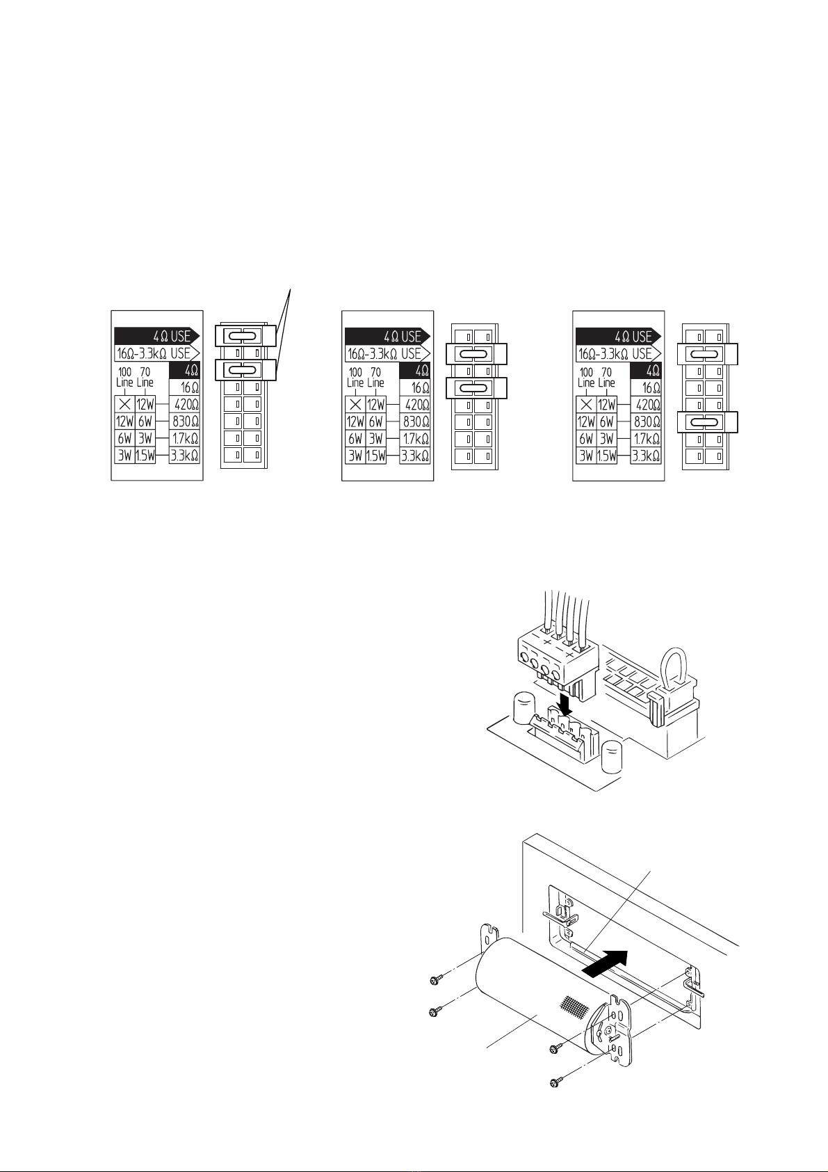
2-4. Attach two impedance selector sockets to the
connector to select the desired impedance. Preset to
830 Ω(12 W for 100 V line and 6 W for 70 V line).
Note
The speaker is designed to be used for both 70 V and
100 V line applications. When using the 100 V line,
do not select the "420 Ω" impedance, since the
speaker itself or power amplifier may be damaged.
2-5. Insert the detachable input connector into the
speaker socket.
Step 3. Mounting the speaker and Trim Piece
3-1. Align the four inward-facing holes in the speaker's
mounting bracket with the corresponding holes in the
Adapter Panel mounting tabs, then mount the
speaker to the panel using the four supplied screws
(M4 x 25 screws with both the spring washers and
plain washers).
Adapter Panel
H-1 speaker
•When selecting 4 Ω•When selecting 16 Ω•When selecting 830 Ω
(preset by the factory)
Impedance selector socket

8
3-2. Loosen the angle adjustment screws. After adjusting
the angle, retighten the screws.
Tip
The mounting angle can be adjusted for up to ±45°.
Since the mounting bracket is marked with mounting
angles at 15° intervals, use this marking as a guide
when adjusting the angle.
3-3. Align the two securing clips on the Trim Piece with
the speaker's two stud screws, then push the Trim
Piece onto the speaker until the Trim Piece is snug to
the wall or ceiling surface.
5.2. Mounting the Speaker to an Electrical Box Using The Adapter Panel
The H-1 speaker system can be mounted to walls or ceilings using an electrical box*. Mount the Adapter
Panel to the electrical box as shown below. Further mounting procedures are the same as detailed in Steps 2
and 3.
* Distance between mounting holes (A) x (B):
254 mm (10") x 66.7 mm (2 5/8") or
255.6 mm (10 1/10") x 55.6 mm (2 3/16")
45°
45°
90゜
15゜
15゜
15゜
Stud screw
Angle adjustment screw
(A)
(B)
Electrical box
Adapter Panel
Trim Piece Stud screw
Securing clip
H-1 speaker
H-1 speaker
Memo
Electrical box mounting screws are attached to the H-1 speaker.

9
5.3. Mounting the Speaker Directly to an Electrical Box
The H1 speaker system can also be mounted directly to an electrical box*. Follow Steps 2 and 3 for
instructions. In this case, use the outward-facing holes in the mounting bracket when mounting to the wall or
ceiling.
* Distance between mounting holes (A) x (B): 254 mm (10") x 66.7 mm (2 5/8") or
255.6 mm (10 1/10") x 55.6 mm (2 3/16")
(A)
(B)
Note: The distance between the wall or ceiling surface and the box bottom surface must be 45 mm or more.
When using the Raco 953 electrical box, be careful in installation because it is shallow.
45 mm or more
5.4. Removing the Trim Piece
When removing the Trim Piece for maintenance or repair,
squeeze its sides by hand to create a gap between the
Trim Piece and wall/ceiling, then insert a screwdriver blade
into the gap and pry off the piece.
Caution
If you raise either right or left side of the Trim Piece by
force, it may be broken. Pull the both sides out evenly and
gradually.
H-1 speaker
Electrical box
Memo
Electrical box mounting screws are
attached to the H-1 speaker.

6. REPAINTING THE GRILLE AND TRIM PIECE
Follow the procedures below to change the color of the
grille.
1. Remove the speaker's angle adjustment screw (1
piece).
2. Detach either of the two mounting brackets attached to
the speaker.
3. Remove the two grille mounting screws from the back of
the speaker.
4. Slide the grille off the speaker.
5. Paint both the grille and Trim Piece.
5-1. Wipe dirt off the grille and Trim Piece with a soft cloth
moistened with a detergent before painting. Do not
use volatile liquids such as thinner.
5-2. Uniformly spray a thin coating of paint over the grille
and Trim Piece changing the spraying positions
gradually.
Notes
• Do not use a roller or brush to paint because the
meshes of the grille could be clogged with paint.
• Use paint that is appropriate for the composition of
the grille and Trim Piece.
Grille: Rolled steel plate
Trim Piece: Fire-resistant ABS resin
• Follow the instructions on the paint when painting.
5-3. After the paint dries, repeat Step 5-2 once or twice to
repaint.
Notes
• Be sure to repeat Step 5-2 at least twice.
• When repainting the front grille, place the grille
upside down so that the surface is painted uniformly.
6. After the paint has dried, remount the grille to the
speaker.
10
Grille
Grille mounting screw
Mounting bracket
Angle adjustment screw
Other manuals for H-1
1
Table of contents
Other Toa Speakers System manuals


Popular Speakers System manuals by other brands




Sondpex
Sondpex Active Speaker System and Digital Music... User manual and installation instructions

JVC
JVC NX-PN7 instructions

Marshall Amplification
Marshall Amplification AR-DM61-BT user manual

Yamaha
Yamaha NX-A01 - Speaker Sys Product bulletin
SE Audiotechnik
SE Audiotechnik I-LINE manual

Gemini
Gemini WRX-843 Series user manual