Toa F-122CU User manual
INSTRUCTION MANUAL
CEILING SPEAKER SYSTEM F-122CU
Please follow the instructions in this manual to obtain the optimum results from this unit.
We also recommend that you keep this manual handy for future reference.
Rev. A

2
TABLE OF CONTENTS
1. SAFETY PRECAUTIONS ............................................................................... 3
2. GENERAL DESCRIPTION ............................................................................. 3
3. FEATURES .......................................................................................................... 4
4. NOMENCLATURE AND DIMENSIONS ..................................................... 4
5. MOUNTING HARDWARE INSTALLATION ............................................... 5
6. WIRING
6.1. Using the Speaker in UL1480 Category UUMW .............................................. 9
6.2. Using the Speaker in UL1480 Category UEAY only
6.2.1. Wiring through hard or flexible conduit ................................................. 10
6.2.2. Wiring with naked cables ...................................................................... 11
7. CABLE CONNECTION TO INPUT CONNECTOR ................................. 12
8. SPEAKER INSTALLATION ........................................................................... 13
9. REMOVING THE SPEAKER FOR MAINTENANCE
9.1. Detaching the Front Grille ............................................................................... 15
9.2. Removing the Speaker ................................................................................... 15
10. REPAINTING THE SPEAKER ...................................................................... 16
11. INPUT OVERLOAD PROTECTION FUNCTION .................................... 16
12. SAFETY AGENCY COMPLIANCE
12.1. Setting to the Following Positions .................................................................. 17
12.2. Setting to 8 Ωor 16 ΩPosition ....................................................................... 17
13. SPECIFICATIONS ............................................................................................ 18
Accessories ............................................................................................................. 18
Optional Component ................................................................................................ 18
3
• Leave the installation to your TOA dealer because
the installation requires expert knowledge.
Improper installation may cause the unit to fall,
resulting in personal injury and/or property
damage.
• Install the unit in a location that can structurally
support the weight of the unit and its mounting
hardware. Doing otherwise may result in the unit
falling down and causing personal injury and/or
property damage.
• Do not use other methods than specified to mount
the unit. Extreme force is applied to the unit and
the unit could fall off, possibly resulting in personal
injuries.
• Attach the safety wire to the unit. If not attached,
the unit could fall off, resulting in personal injury.
• Tighten each screw securely. Ensure that the unit
has no loose joints after installation to prevent
accidents that could result in personal injury.
• Never hold the diffuser section as a handle to carry
the unit during installation. If the diffuser breaks off,
the unit could fall from an elevated position,
resulting in possible personal injury.
• Use the specified mounting hardware in
combination. Doing otherwise may cause the unit
or component to fall off, resulting in personal injury.
• Should the following irregularity be found during
use, immediately stop operating the unit and
contact your nearest TOA dealer. Further attempt
to use under this condition may cause fire or
electric shock.
· If you detect smoke or a strange smell coming
from the unit
· If no tone sounds
• Avoid installing the unit in humid or dusty locations,
in locations exposed to the direct sunlight, near the
heaters, or in locations generating sooty smoke or
steam as doing otherwise may result in fire or
electric shock.
• Do not operate the unit for an extended period of
time with the sound distorting. This is an indication
of a malfunction, which in turn can cause heat to
generate and result in a fire.
CAUTION
1. SAFETY PRECAUTIONS
• Be sure to read the instructions in this section carefully before use.
• Make sure to observe the instructions in this manual as the conventions of safety symbols and messages
regarded as very important precautions are included.
• We also recommend you keep this instruction manual handy for future reference.
Safety Symbol and Message Conventions
Safety symbols and messages described below are used in this manual to prevent bodily injury and property
damage which could result from mishandling. Before operating your product, read this manual first and
understand the safety symbols and messages so you are thoroughly aware of the potential safety hazards.
WARNING
Indicates a potentially hazardous situation which, if mishandled, could
result in death or serious personal injury.
Indicates a potentially hazardous situation which, if mishandled, could
result in moderate or minor personal injury, and/or property damage.
WARNING
CAUTION
2. GENERAL DESCRIPTION
The F-122CU is a flush-mounted ceiling speaker that offers a wide frequency range of high-quality sound
output. Use of its supplied mounting hardware and optional HY-TB1 Tile Bar Bridge permits it to be versatilely
mounted to match a wide range of applications and installation locations.

4
3. FEATURES
• Bass-reflex speaker system designed to provide a wide frequency range and high power handling capability.
• Wide-dispersion flush-mount ceiling speaker design employs unique acoustic construction to realize a wide
area of coverage. Uniform sound output levels are achievable not only directly under the speaker, but also
over a wide radius.
• Because the speaker is provided with both low- and high-impedance operating capability, it can be used in
many different applications. Front panel-mounted input selector switch permits easy verification and change
of current impedance settings.
• Easy installation. Can be quickly and accurately mounted to ceilings.
• Rotating front grille can be installed quickly and conveniently.
• Attractive exterior design specially created by an interior designer blends naturally with any architectural
space, enhancing the immediate area's sense of harmony.
4. NOMENCLATURE AND DIMENSIONS
[Ceiling mounting]
Ceiling reinforcement ring
(accessory)
Mounting hole: ø200 (7 7/8)
Ceiling panel
Max. 202 (7 61/64)
Max. 37 (1 29/64)
Safety wire (accessory)
ø230 (9 1/16)
40 (1 37/64)
238 (9 3/8)
ø195 (7 43/64)
Approx. 600 (23 5/8)
[Front] [Side]
[Rear] Safety wire hook
Choke bracketConnector cover
Front grille (accessory)
Unit: mm (inches)

5
5. MOUNTING HARDWARE INSTALLATION
Before mounting the speaker, determine the most appropriate method for the existing ceiling structure.
Be sure to use an optional HY-TB1 Tile Bar Bridge in combination with the supplied ceiling
reinforcement ring.
[Installation view on Drop Ceilings]
Because the bridge rails are 603 mm (23 47/64") in length, be sure to match them to the ceiling tile size during
installation.
Caution
Set the bridge rails so that both ends fit securely into the T-grids, even if the ceiling tile accidentally falls off.
Ceiling tileT-grid
Bridge rail
HY-TB1
(optional)
Ceiling reinforcement ring (accessory)
Reinforcement ring mounting screw
Tie-plate mounting screw
Tie-plate
(preinstalled on Bridge rail)
[Installation view on Dry Wall Ceilings]
Caution
Only install the Tile Bar Bridge on ceiling frames that can structurally support the weight of the speaker(s).
Ceiling panel
Reinforcement ring mounting screw
HY-TB1
(optional)
Bridge rail
Ceiling reinforcement ring (accessory)
Ceiling frame
Tie-plate mounting screw
Tie-plate
(preinstalled on Bridge rail)

6
Ceiling panel
ø200 ±5 mm (7 7/8±13/64")
Step 1. Cut a ø200 mm (7 7/8") hole in the ceiling.
Use the supplied paper pattern to position and trace the hole.
Step 2. Install the HY-TB1 in the ceiling.
Loosen the two reinforcement ring mounting screws in each tie-plate to the point that they do not fall
out of their holes.
Tie-plate mounting screw
Reinforcement ring mounting screws
(Leave these screws loose.)
Bridge rail
HY-TB1
(optional)
Tie-plate
[For Drop Ceiling]
• Mounting to 2-foot tiles
Align the two bridge rails as shown in the figure
at right.
• Mounting to 600 mm tiles
Align the two bridge rails diagonally at an angle
of 10°–15°.
T- g r i d
2-foot tile HY-TB1 (optional)
T- g r i d
600 mm tile
HY-TB1 (optional)
10°–15°

7
Step 4. Attach the ceiling reinforcement ring to
each tie-plate using 2 reinforcement ring
mounting screws.
Ceiling reinforcement ring
Reinforcement ring mounting screw
Tie-plate
Fit closely to the back surface
of the ceiling panel.
1
2
Ceiling reinforcement ring
Tie-plate mounting screw
Tie-plate
If the ceiling reinforcement ring does not line
up accurately with the ceiling mounting hole,
adjust its position by either loosening the tie-
plate mounting screws and sliding the tie-
plate into correct position, or by shifting the
tie-plate mounting screws to the appropriate
holes in the Tile Bridge rails.
The ceiling reinforcement ring can be moved
in the direction indicated by the arrows.
Note
Be sure to tighten the tie-plate mounting
screws after completing the adjustment.
Fold the reinforcement ring in half* and insert it
through the mounting hole in the ceiling panel,
then open it with its tabs facing up.
Place the ring on the ceiling panel aligning it
with the mounting hole.
* The reinforcement ring is too large to be
inserted into the mounting hole unless folded.
Mounting hole
Ceiling reinforcement ring
(accessory)
Reinforcement ring placed on the ceiling panel
These tabs must
face upward,
away from the hole.
Step 3. Place the supplied reinforcement ring on the ceiling panel.
8
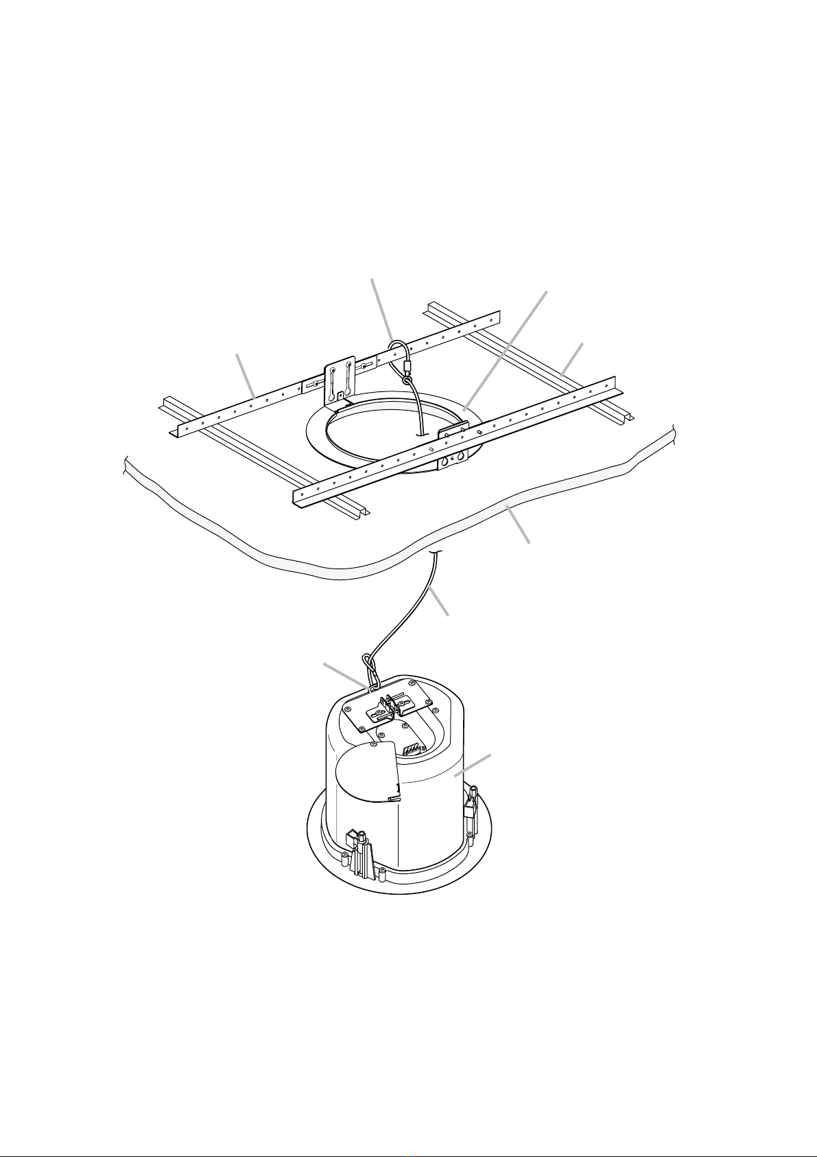
Step 5. Attach a safety wire to prevent the speaker from accidentally falling.
To attach, tie one end of the supplied safety wire around the speaker's safety wire hook, and tie its
snap ring around the installed HY-TB1 or a solid structure.
Note
When there is no gap between the bridge rails and the ceiling panel, to secure the safety wire, tie the
wire around a solid structure (pipe, building frame, etc.).
Speaker unit
Ceiling panel
Ceiling frame
Safety wire (accessory)
Safety wire (accessory)
HY-TB1 (optional)
Ceiling reinforcement ring
(accessory)
Safety wire hook
9
6. WIRING
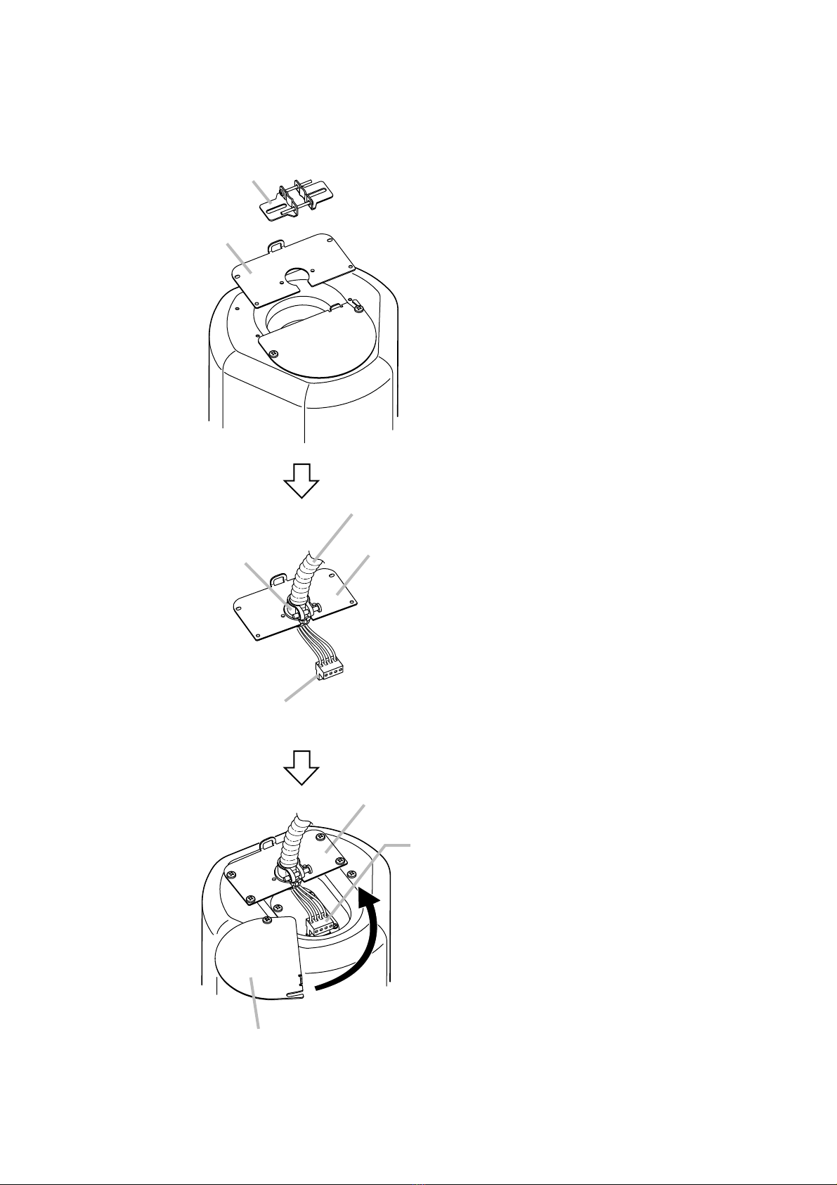
6.1. Using the Speaker in UL1480 Category UUMW
Choke bracket
Cover plate
Cover plate
Connector cover
After completing the speaker cable connection, turn the connector cover
in the direction indicated by the arrow, and fix the cover with 2 screws.
Remove the choke bracket and the cover plate
from the speaker.
Note
The removed choke bracket is not used.
Flexible metal conduit (3/8" or 1/2")
Conduit fitting
Detachable input connector
To install this speaker as a fire alarm signaling
service UUMW, use flexible conduit of 3/8 or 1/2
inch trade size and the UL514B listed conduit
fitting of the same trade size.
Mount the conduit fitting to the cover plate.
Connect the conduit to the fitting, and wire the
detachable input connector.
(For wiring the input connector, refer to p. 12.)
Replace the cover plate to the speaker.
Plug the wired input connector into the speaker's
socket.
10
6.2. Using the Speaker in UL1480 Category UEAY only
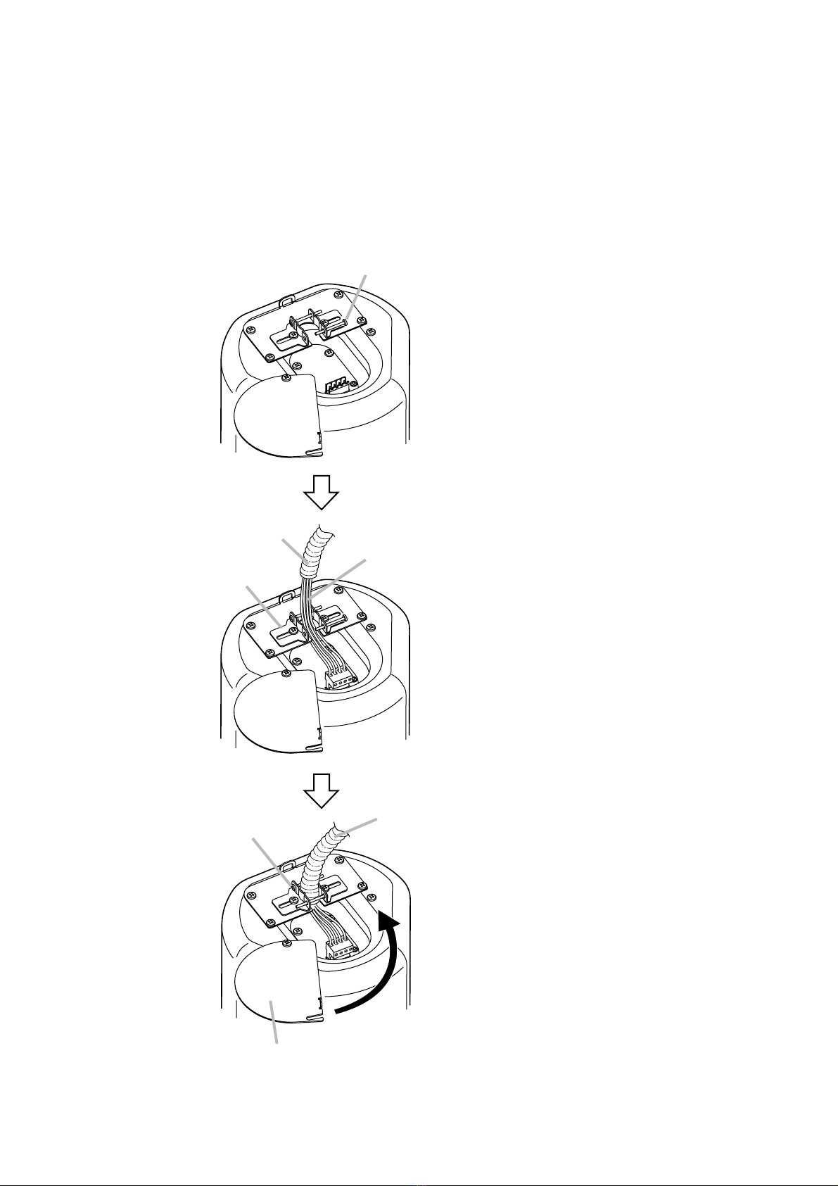
6.2.1. Wiring through hard or flexible conduit
Note
The choke bracket equipped with the speaker has not been evaluated by UL, for conduit connection and
UL514B Standard.
Flexible conduit of 3/8 or 1/2 inch trade size and the UL514B conduit fitting of the same trade size can also be
used. For the method of conduit connection, refer to p. 9.
Loosen the screw to allow the speaker cable to pass through.
Choke bracket
Flexible conduit
Retighten the screw to fix
the flexible conduit.
Note
Ensure that the flexible conduit is securely fixed.
Connector cover
After completing the speaker cable connection, turn the connector cover
in the direction indicated by the arrow, and fix the cover with 2 screws.
Plug the wired input connector into the speaker's socket,
then pull the speaker cable from the choke bracket.
(For wiring the input connector, refer to p. 12.)
Accommodating larger diameter conduit
The choke bracket accommodates up to 3/8-inch
(9.5 mm) flexible conduit. When larger diameter
conduit should be fit, use a suitable fitting
commercially available by replacing the existing
choke bracket with it. Detaching the choke
bracket by unscrewing it exposes a 7/8-inch (22
mm) hole. Install the alternate fitting there.
Other manuals for F-122CU
2
Table of contents
Other Toa Speakers System manuals


Popular Speakers System manuals by other brands


Sondpex
Sondpex Active Speaker System and Digital Music... User manual and installation instructions

JVC
JVC NX-PN7 instructions

Marshall Amplification
Marshall Amplification AR-DM61-BT user manual

Yamaha
Yamaha NX-A01 - Speaker Sys Product bulletin

SE Audiotechnik
SE Audiotechnik I-LINE manual

Gemini
Gemini WRX-843 Series user manual