Toa SR-C8L User manual

Thank you for purchasing TOA Line Array Speaker. Please carefully follow the instructions in this manual to ensure
long, trouble-free use of your equipment
LINE ARRAY SPEAKERS
RIGGING FRAME
RIGGING SUPPORT BRACKET
TILT JOINT BRACKET
CLUSTER BRACKET
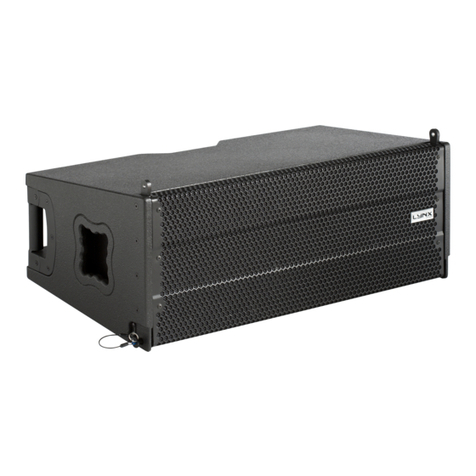
SR-C8L
SR-C8S
SR-C15B
SR-RF8
SR-SB8
SR-TP8
SR-CL8
OPERATING INSTRUCTIONS
Note that casters must be prepared separately.

TABLE OF CONTENTS
2
1. SAFETY PRECAUTIONS ............................................................................................... 3
2. GENERAL DESCRIPTION ............................................................................................. 5
3. FEATURES .......................................................................................................................... 5
4. INSTALLATION PRECAUTIONS ................................................................................. 5
5. DIMENSIONAL DIAGRAMS
5.1. Speaker Systems
5.1.1. SR-C8L Line array speaker ................................................................................... 6
5.1.2. SR-C8S Line array speaker .................................................................................. 6
5.2. Sub-Woofer Speaker System
5.2.1. SR-C15B Line array speaker ................................................................................ 7
5.3. Frame and Brackets
5.3.1. SR-RF8 Rigging frame .......................................................................................... 7
5.3.2. SR-SB8 Rigging support bracket .......................................................................... 8
5.3.3. SR-TP8 Tilt joint bracket ....................................................................................... 8
5.3.4. SR-CL8 Cluster bracket ........................................................................................ 8
6. BI-AMPLIFIER AND SINGLE-AMPLIFIER OPERATIONS
6.1. Bi-Amplifier Operation ...................................................................................................... 9
6.2. Single-Amplifier Operation ............................................................................................... 9
7. SWITCHING TO SINGLE-AMPLIFIER OPERATION MODE ............................ 10
8. DIGITAL PROCESSOR SETTINGS
8.1. SR-C8L and SR-C8S Systems ....................................................................................... 11
8.2. Combined SR-C8L or SR-C8S and SR-C15B Systems ................................................. 12
9. FLYING SYSTEMS USING THE SR-RF8 RIGGING FRAME
9.1. Flying System Outline .................................................................................................... 13
9.2. Assembling the SR-RF8 Rigging Frame ........................................................................ 15
9.3. Connecting the Rigging Frame to the Speaker .............................................................. 16
9.4. Connection Between Speakers ...................................................................................... 17
9.5. About the Flying Installations ......................................................................................... 18
10.
INSTALLING THE FLYING SYSTEM USING THE SR-CL8 CLUSTER BRACKET
10.1. Flying System Outline .................................................................................................. 19
10.2. Vertical Flying Installation ............................................................................................. 19
10.3. Horizontal Flying ........................................................................................................... 21
11. SPEAKER STACKING
11.1. Stack System Outline .................................................................................................... 23
11.2. Assembling the SR-RF8 Rigging Frame ....................................................................... 24
11.3. Connecting the Rigging Frame to the Speaker ............................................................. 25
11.4. Connections Between Speakers ................................................................................... 25
11.5. About Stacking ............................................................................................................. 26
12. USING THE SR-SB8 RIGGING SUPPORT BRACKET ...................................... 27
12.1. Level Adjuster Installation ............................................................................................ 27
12.2. Rigging Support Bracket Installation ............................................................................ 27
12.3. Frequent Attachment and Detachment of the Rigging Support Bracket ...................... 28
12.4. Adjust the Height With a Level Adjuster to Prevent Unstable Installation .................... 28
13. TILTING THE SPEAKER DOWNWARD .................................................................. 29
14. SPECIFICATIONS
14.1. SR-C8L and SR-C8S .................................................................................................... 30
14.2. SR-C15B ....................................................................................................................... 30
14.3. SR-RF8 ......................................................................................................................... 31
14.4. SR-SB8 ......................................................................................................................... 31
14.5. SR-TP8.......................................................................................................................... 31
14.6. SR-CL8 ......................................................................................................................... 31

1. SAFETY PRECAUTIONS
3
When Installing the Unit
• Avoid installing or mounting the unit in unstable
locations, such as on a rickety table or a slanted
surface. Doing so may result in the unit falling
down and causing personal injury and/or property
damage.
• Refer all installation work to the dealer from whom
the speaker was purchased. Installation for flying
requires extensive technical knowledge and
experience. The speaker may fall off if incorrectly
installed, resulting in possible personal injury.
• Flying precautions.
Be sure to follow the instructions below. Otherwise,
the suspension wires or belts may be off or snap
and the speaker may fall off, causing personal
injury.
· Check to confirm that the suspension wires and
belts are strong enough to
· The connectors of the suspension wires and belts
must be securely linked with those of the
speaker.
· All parts and components (such as enclosures,
metal pieces, and screws) must be free from any
deformation, crack, and corrosion.
· Be sure to use screws supplied with the optional
flying hardware when installing the speaker using
such hardware.
• Install the unit only in a location that can
structurally support the weight of the unit and the
mounting bracket. Doing otherwise may result in
the unit falling down and causing personal injury
and/or property damage.
• Since the unit is designed for in-door use, do not
install it outdoors. If installed outdoors, the aging of
parts causes the unit to fall off, resulting in personal
injury. Also, when it gets wet with rain, there is a
danger of electric shock.
• Owing to the unit's size and weight, be sure that at
least two persons are available to install the unit.
Failure to do so could result in personal injury.
When Installing the Unit
• Do not use other methods than specified to mount
the bracket. Extreme force is applied to the unit
and the unit could fall off, possibly resulting in
personal injuries.
• Use nuts and bolts that are appropriate for the
ceiling's or wall's material and structure. Failure to
do so may cause the unit to fall, resulting in
material damage and possible personal injury.
• Tighten each nut and bolt securely. Ensure that the
bracket has no loose joints after installation to
prevent accidents that could result in personal
injury.
• Use the specified mounting bracket in combination.
Doing otherwise may cause the unit or component
to fall off, resulting in personal injury.
• Do not mount the unit in locations exposed to
constant vibration. The mounting bracket can be
damaged by excessive vibration, potentially
causing the unit to fall, which could result in
personal injury.
• Do not install the unit in indoor swimming pools or
such locations where corrosion may occur easily.
The parts deteriorate if corroded, causing the unit
to fall, which could result in personal injury.
• Be sure to read this safety instructions in this section carefully in prior to use.
• Be sure to follow all the precautionary instructions in this section, which contain important warnings and/or
cautions regarding safety.
• After reading, keep this manual handy for future reference.
Safety Symbol and Message Conventions
Safety symbols and messages described below are used in this manual to prevent bodily injury and property
damage which could result from mishandling. Before operating your product, read this manual first and
understand the safety symbols and messages so you are thoroughly aware of the potential safety hazards.
WARNING
Indicates a potentially hazardous situation which, if mishandled, could
result in death or serious personal injury.
Indicates a potentially hazardous situation which, if mishandled, could
result in moderate or minor injury, and/or property damage.
WARNING
CAUTION

4
When the Unit is in Use
• Do not place heavy objects on the unit as this may
cause it to fall or break which may result in
personal injury and/or property damage. In
addition, the object itself may fall off and cause
injury and/or damage.
• Do not operate the unit for an extended period of
time with the sound distorting. Doing so may cause
the connected speakers to heat, resulting in a fire.
• Do not stand or sit on, nor hang down from the unit
as this may cause it to fall down or drop, resulting
in personal injury and/or property damage.
• To avoid risks, warn others to stay away from the
speaker or not to lean against it. Otherwise people
may trip over a Rigging Support Bracket or the
speaker may fall down, causing personal injury.
• Have the unit checked periodically by the shop
from where it was purchased. Failure to do so may
result in corrosion or damage to the speaker or the
unit that could cause it to fall, possibly causing
personal injury.
CAUTION

2. GENERAL DESCRIPTION
3. FEATURES
4. INSTALLATION PRECAUTIONS
5
TOA's lineup of line array speakers employs TOA's unique wave front control technology to create a sound
field that offers clear reproduction and uniform sound dispersion.
This lineup includes versions offering either 5 degrees or 15 degrees of angled vertical directivity, as well as
sub-woofer configured types.
The use of optional support brackets allows the line array speakers to be used in many applications as
permanent sound system installations.
• TOA's unique wave front control technology creates a uniform sound distribution field with interference-free
high frequency output, realizing high-clarity acoustic characteristics and long sound transmission
capabilities.
• The SR-C8L is a two-way speaker mounting a high-power 20 cm woofer and two compression drivers, and
featuring a 5 degree angle of vertical directivity and 110 degrees of horizontal. It is ideal for long distance
applications and can be powered by either one or two amplifiers.
• The SR-C8S is a two-way speaker mounting a high-power 20 cm woofer and two compression drivers, and
featuring a 15 degree angle of vertical directivity and 110 degrees of horizontal. It is ideal for shorter
distance applications and can be powered by either one or two amplifiers.
• By combining the long-distance SR-8L and short-distance SR-8S, a line array speaker system can be built
to support a variety of applications.
• The SR-C15B sub-woofer employs a large-diameter 38 cm woofer with high power handling capabilities,
and is designed to be used in conjunction with the SR-C8L or SR-C8S line array speakers.
• The line array speakers are designed to allow easy rear access for maintenance work.
• Overlap angles between individual speakers can be set in 1 degree units between 0 and 5 degrees when
constructing the line array speaker, making it possible to flexibly control speaker directivity.
• The line array speaker can be stacked or suspended with the additional use of the SR-RF8 Rigging Frame.
Since this speaker system is designed exclusively for indoor use, be sure to install it only in locations isolated
from weather and temperature extremes.
Also, to prevent equipment malfunctions, do not install the speaker in locations exposed to both high
temperatures and high humidity, such as indoor swimming pool facilities.

5. DIMENSIONAL DIAGRAMS
6
5.1. Speaker Systems
5.1.1. SR-C8L Line array speaker
(Front view)(Left side view)
Unit: mm
(Rear view)
(Right side view)
526.6 [20.73"]
470 [18.5"]
5°
293 [11.54"]
259.6 [10.22"]
296 [11.65"]
5.1.2. SR-C8S Line array speaker
(Front view)(Left side view)
Unit: mm
(Rear view)
(Right side view)
470 [18.5"]
526.6 [20.73"]
15°
258.8 [10.19"]
293 [11.53"]
294 [11.57"]

7
(Bottom view)
(Left side view)
Unit: mm
(Top view)
(Front view)
(Right side view)
16-M10
(For caster mounting)
15-ø20 [ø0.79"]
14 [0.55"]
6 [0.24"] 498 [19.61"]
510 [20.08"]
377 [14.84"]
93 [3.66"]
36 [1.42"]
25 [0.98"]
71 [2.8"]
95 [3.74"]
71 [2.8"]
95 [3.74"]
50 [1.97"] 4.5 [0.18"]
6.4 [0.25"]
50 [1.97"]
155.5 [6.12"]
690 [27.17"]
595 [23.43"]
85 [3.35"]
167 [6.58"]
105 [4.13"]
5.3. Frame and Brackets
5.3.1. SR-RF8 Rigging frame
(Front view)(Left side view)
Unit: mm
(Rear view)
(Right side view)
526.6 [20.73"]
470 [18.5"]
540 [21.26"]
594.8 [23.42"]
550 [21.65"]
5.2. Sub-Woofer Speaker System
5.2.1. SR-C15B Line array speaker

8
Unit: mm
4-ø10.5 [ø0.41"]
15-ø13 [ø0.51"]
[1.46"]
[1.57"]
37
40
13 [0.51"]
45 [1.77"]
25 [0.98"]
18 [0.71"]
15 [0.59"] 20 [0.79"]
310 [12.2"]
4.5 [0.18"]
5.3.4 SR-CL8 Cluster bracket
Unit: mm
120.6 [4.75"] 6.4 [0.25"]
294 [11.57"]
14 [0.55"]
5.3.3. SR-TP8 Tilt joint bracket
(Front view)
Unit: mm
(Top view)
2-ø10.5 [ø0.41"]
517.5 [20.37"]
52 [2.05"]
208 [8.19"]
275.8 [10.86"]
350 [13.78"]
40 [1.57"]
150 [5.91"] 20 [0.79"]
270 [10.63"]
135°
5.3.2 SR-SB8 Rigging support bracket

6. BI-AMPLIFIER AND SINGLE-AMPLIFIER OPERATIONS
9
The SR-C8 series speakers are supplied from the factory set up for bi-amplifier operation. However, this
default specification can be switched to single-amplifier operation mode by simply changing the position of an
internal connector. (Refer to page 10. "Switching to Single-Amplifier Operation Mode")
6.1. Bi-Amplifier Operation
6.1.1. System diagram
Mixer/
preamplifier
Digital
processor
Power amplifier
Passive
network
SR-C8L/C8S
LOW
HIGH
Tweeter
Woofer
Passive
network Woofer
Tweeter
Screw terminal
Neutrik NL4MP connector
Input terminal panel
INPUT
INPUT
THROUGH
THROUGH 2
1
1
2
1
21
2
Mixer/
preamplifier
Digital
processor
Power amplifier
SR-C8L/C8S
LOW
HIGH
LOW
HIGH
Tweeter
Woofer
LOW
HIGH
LOW
HIGH 2
1
21
2
1
21
Screw terminal
Neutrik NL4MP connector
Input terminal panel
Woofer
Tweeter
6.2. Single-Amplifier Operation
6.2.1. System diagram
6.1.2. Internal wiring diagram
6.2.2. Internal wiring diagram

7. SWITCHING TO SINGLE-AMPLIFIER OPERATION MODE
10
To switch the speaker's bi-amplifier operation mode to single-amplifier operation, remove the speaker's rear
input panel and change the speaker's internal wiring.
Switching Power Modes
Step 1. Remove the four screws securing the input terminal panel and pull out the panel.
Step 2. Pull out a short length of the wiring connected to the back side of the input panel.
Step 3. Disconnect and switch the two pairs of connected connectors so that the two marked and unmarked
connector halves match up.
Step 4. Reinstall the input terminal panel using the four removed screws.
Step 5. Attach the supplied seals to the input terminal panel to change the indication.
Switching connectors
Mark
Input indication seal for single-amplifier operation
(accessory)
Rating seal for single-amplifier
operation (accessory)
Changing input terminal panel indication
Panel mounting screws
Input terminal panel
1, 4 2
3
5
This manual suits for next models
6
Table of contents
Other Toa Speakers System manuals
Popular Speakers System manuals by other brands

Sondpex
Sondpex Active Speaker System and Digital Music... User manual and installation instructions

JVC
JVC NX-PN7 instructions

Marshall Amplification
Marshall Amplification AR-DM61-BT user manual

Yamaha
Yamaha NX-A01 - Speaker Sys Product bulletin

SE Audiotechnik
SE Audiotechnik I-LINE manual

Gemini
Gemini WRX-843 Series user manual