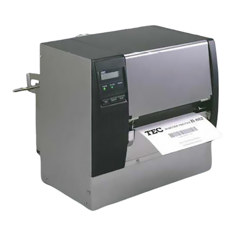
TEC B-450 SERIES User manual

TEC Thermal Printer
B-450 SERIES
Original Dec., 1998
(Revision May, 2000)
PRINTED IN JAPAN
Maintenance Manual
Document No. EO18-33003A

EO18-33003A
TABLE OF CONTENTS
1. UNPACKING ...................................................................................................... 1- 1
1.1 PROCEDURE ............................................................................................. 1- 1
1.2 CHECKS ..................................................................................................... 1- 2
2. MAJOR UNIT REPLACEMENT.......................................................................... 2- 1
2.1 REPLACING THE CPU PC BOARD........................................................... 2- 1
2.2 REPLACING THE MOTOR......................................................................... 2- 3
2.2.1 Ribbon Motor.................................................................................... 2- 3
2.2.2 Stepping Motor................................................................................. 2- 5
2.3 REPLACING THE PS UNIT ........................................................................ 2- 6
2.4 REPLACING THE PRINT HEAD ............................................................... 2-10
2.5 REPLACING THE HEAD CONTROL PC BOARD
(FOR B-452-HS MODEL)........................................................................... 2-11
2.6 REPLACING THE MEDIA SENSOR.......................................................... 2-12
2.6.1 B-452-TS Model .............................................................................. 2-12
2.6.2 B-452-HS Model.............................................................................. 2-15
2.7 REPLACING THE 600 DPI EXPIO PC BOARD
(FOR B-452-HS MODEL)........................................................................... 2-18
3. INSTALLATION PROCEDURE FOR THE OPTIONAL EQUIPMENT................ 3- 1
3.1 CUTTER MODULE (B-7204-QM) ............................................................... 3- 1
3.1.1 Pacing List........................................................................................ 3- 1
3.1.2 Installation Procedure ...................................................................... 3- 1
3.2 CENTRONICS INTERFACE BOARD (B-7704-C-QM) ............................... 3- 7
3.2.1 Packing List...................................................................................... 3- 7
3.2.2 Installation Procedure ...................................................................... 3- 7
3.3 EXPANSION I/O INTERFACE BOARD (B-7704-IO-QM) ........................... 3- 9
3.3.1 Packing List...................................................................................... 3- 9
3.3.2 Installation Procedure ...................................................................... 3- 9
3.4 EXPANSION MEMORY BOARD (B-7804-E1M-QM)................................. 3-11
3.4.1 Packing List..................................................................................... 3-11
3.4.2 Installation Procedure ..................................................................... 3-11
3.5 LAN I/F BOARD (B-7704-LAN-QM) ........................................................... 3-12
3.5.1 Packing List..................................................................................... 3-12
3.5.2 Installation Procedure ..................................................................... 3-12
3.6 PROGRAMMABLE KEYBOARD (KB-80-QM) ........................................... 3-14
3.6.1 Installation Procedure ..................................................................... 3-14
3.7 STRIP MODULE (B-7904-H-QM) .............................................................. 3-15
3.7.1 Packing List..................................................................................... 3-15
3.7.2 Installation Procedure ..................................................................... 3-16
4. TROUBLESHOOTING........................................................................................ 4- 1
5. ONLINE OPERATION ........................................................................................ 5- 1
5.1 RESET OPERATION .................................................................................. 5- 1
5.1.1 When using the KB-80-QM Optional Keyboard ............................... 5- 1
5.1.2 When using the operation panel ...................................................... 5- 3
Page

EO18-33003A
Page
6. DIAG. TEST OPERATION.................................................................................. 6- 1
6.1 OUTLINE OF THE DIAG. TEST OPERATION ........................................... 6- 1
6.1.1 When using the KB-80-QM Optional Keyboard ............................... 6- 1
6.1.2 When using the operation panel ...................................................... 6- 2
6.2 SELF TEST MODE (When using the KB-80-QM Optional Keyboard) ........ 6- 3
6.2.1 Maintenance Counter and Automatic Diagnostic Printings.............. 6- 3
6.3 PARAMETER SETTING MODE
(When using the KB-80-QM Optional Keyboard) ....................................... 6-11
6.3.1 Feed Length Fine Adjustment ......................................................... 6-13
6.3.2 Cut/Strip Position Fine Adjustment ................................................. 6-14
6.3.3 Back Feed Length Fine Adjustment ................................................ 6-15
6.3.4 X Axis Fine Adjustment ................................................................... 6-20
6.3.5 Print Tone Fine Adjustment (Thermal Transfer Print) ..................... 6-22
6.3.6 Print Tone Fine Adjustment (Thermal Direct Print) ......................... 6-23
6.3.7 Font Code Selection........................................................................ 6-24
6.3.8 Font Zero Selection......................................................................... 6-25
6.3.9 Transmission Control Mode Selection ............................................ 6-26
6.3.10 Control Code Selection ................................................................... 6-27
6.3.11 Ribbon Take-up Motor Voltage Fine Adjustment ............................ 6-28
6.3.12 Ribbon Feed Motor Voltage Fine Adjustment ................................. 6-29
6.3.13 Strip Wait Status Setting ................................................................. 6-30
6.3.14 Threshold Manual Fine Adjustment for the Black Mark Sensor ...... 6-31
6.3.15 Threshold Manual Fine Adjustment for the Feed Gap Sensor........ 6-32
6.3.16 Kanji Code Selection....................................................................... 6-33
6.3.17 Feed Speed Adjustment.................................................................. 6-34
6.3.18 Character Code 5CH Selection....................................................... 6-36
6.3.19 Euro Font Code Setting................................................................... 6-37
6.4 TEST PRINT MODE (When using the KB-80-QM Optional Keyboard) ..... 6-38
6.5 SENSOR SETTING MODE
(When using the KB-80-QM Optional Keyboard) ....................................... 6-44
6.5.1 Thermistor Check............................................................................ 6-44
6.5.2 Black Mark Sensor Adjustment ....................................................... 6-45
6.5.3 Feed Gap Sensor Adjustment......................................................... 6-46
6.6 SENSOR SETTING MODE (When using the operation panel) ................. 6-47
6.7 THRESHOLD SETTING (When using the operation panel) ...................... 6-48
6.8 RAM CLEAR MODE (When using the KB-80-QM Optional Keyboard) ..... 6-49
6.8.1 Maintenance Counter Clear ............................................................ 6-51
6.8.2 Parameter Clear.............................................................................. 6-52
6.9 RAM CLEAR MODE (When using the operation panel) ............................ 6-53
6.9.1 Maintenance Counter Clear ............................................................ 6-53
6.9.2 Parameter Clear.............................................................................. 6-53
6.10LAN I/F SETTING MODE
(When using the KB-80-QM Optional Keyboard) ....................................... 6-54
6.11HEAD BROKEN ELEMENT CHECK (B-452-HS MODEL) ........................ 6-56

EO18-33003A
7. PROGRAM DOWN LOAD FOR PRINTER......................................................... 7- 1
7.1 FLOPPY DISK............................................................................................. 7- 1
7.2 SETUP ........................................................................................................ 7- 1
7.2.1 Connecting the Printer to the PC ..................................................... 7- 1
7.2.2 Program Download FDK (3.5”, 2HD, 1.44MB) ................................. 7- 1
7.3 DOWN LOAD PROCEDURE (DOS Version).............................................. 7- 2
7.4 ERROR CODE............................................................................................ 7- 3
7.5 DOWN LOAD PROCEDURE (WINDOWS Version) ................................... 7- 4
7.6 ERROR MESSAGE .................................................................................... 7- 7
8. PROGRAM DOWN LOAD FOR KEYBOARD .................................................... 8- 1
8.1 OUTLINE..................................................................................................... 8- 1
8.2 SETUP ........................................................................................................ 8- 1
8.3 BLOCK DIAGRAM FOR FILE LOADING (CONNECTION) ........................ 8- 1
8.4 DOWN LOAD PROCEDURE ...................................................................... 8- 2
8.4.1 Program download mode ................................................................. 8- 2
8.4.2 Program file maintenance mode (Deleting program files)................ 8- 3
8.5 DOWNLOAD PROCEDURE (WINDOWS Version) .................................... 8- 4
CAUTION:
1. This manual may not be copied in whole or in part without prior written permission of
TOSHIBA TEC.
2. The contents of this manual may be changed without notification.
3. Please refer to your local Authorized Service representative with regard to any queries you
may have in this manual.
Copyright © 2000
by TOSHIBA TEC CORPORATION
All Rights Reserved
570 Ohito, Ohito-cho, Tagata-gun, Shizuoka-ken, JAPAN
Page

1-1
EO18-33003A
1. UNPACKING
Fig. 1-1
1. UNPACKING
1.1 PROCEDURE
1) Open the carton.
2) Unpack the side pads (L)/(R) and cushions and the printer from the carton.
3) Unpack the accessories from the carton.
1.1 PROCEDURE
Side Pad (R) Printer Owner’s Manual
Cushion
Cushion
Carton Power Cord
Side Pad (L)
Supply
Holder
Base
Supply Holder
Dust Cover Base
Dust Cover Ass’y
Carton
Ribbon
CD ROM
Label
Centronics Interface Cable
Accessory
(For B-452-QP-PAC model)
Accessory
(B-452-HS Mosel)

1-2
EO18-33003A
1. UNPACKING
1.2 CHECKS
5) Open the top cover.
6) Remove the three pieces of tape and print head pad from the printer.
7) Place the printer on a level surface.
1.2 CHECKS
1) Check for damage or scratches on the printer.
2) Confirm that none of the accessories are missing.
NOTE: Keep the carton, pads and cushions for later transport.
Fig. 1-3
4) Remove the three pieces of tape from the printer.
Fig. 1-2
Tape
Tape
Print Head Pad
Print Head
Platen

2-1
EO18-33003A
2. MAJOR UNIT REPLACEMENT
WARNING!
Disconnect power cord before replacing important parts.
2.1 REPLACING THE CPU PC BOARD
2. MAJOR UNIT REPLACEMENT
■Lubrication
CAUTION: 1) Lubrication: During parts replacement
2) Kinds of oil: Kinds of oil: FLOIL G-488: 1Kg can. (Part No. 19454906001).
Any machine is generally in its best condition when delivered; therefore, it is necessary to try to keep
this condition. Unexpected failure occurs due to lack of ioil, debris or dust. To keep its best condition,
periodicallycleanthemachineandapplyproperkindsofoiltoeachpartinwhichlubricationisneeded.
Although the frequency of lubrication varies according to how much the machine is used, at least it is
necessary to lubricate before the machine becomes dry. It is also necessary to wipe off excessibe oil
as it collects dirt.
Fig. 2-1
2.1 REPLACING THE CPU PC BOARD
NOTE: FortheB-452-HSmodel,thefollowingPCboardsneedtoberemovedbeforeremovingtheCPU
PC board. Refer to the sections below.
Head Control PC Board (Refer to Section2.5.)
600 DPI EXPIO PC board (Refer to Section 2.7.)
Centronics interface Board (Refer to Section 3.2.)
1) Turn the power off.
2) Open the top cover.
3) Remove the two PT-3x10 screws to detach the top cover.
Top Cover PT-3x10 Screw Top Cover
CAUTION: Do not spray the inside of the printer with lubricants. Unsuitable oil can dam-
age the machanism.
2-2
EO18-33003A
2. MAJOR UNIT REPLACEMENT
2.1 REPLACING THE CPU PC BOARD
5) RemovethefivePT-3x10screws,the two SMW-3x6 screws andthe ground wire todetach the CPU
PC board.
6) Replace the CPU PC board with a new one, and then reassemble in the reverse order of removal.
Fig. 2-3
CPU PC Board SMW-3x6 Screw PT-3x10 Screw SMW-3x6 Screw
PT-3x10 Screw Ground Wire CPU PC Board PT-3x10 Screw
Fig. 2-2
4) Disconnectthe nine harnessesfromCN3to CN5,CN9,CN12,CN13, CN14, CN20andCN21 on the
CPU PC board.
CN13
CN20
CN12
CN9
CN5
CN4
CN3
CN21
CPU PC Board
CN14

2-3
EO18-33003A
2. MAJOR UNIT REPLACEMENT
2.2 REPLACING THE MOTOR
Before removing the motors, refer to Section 2.1 to detach the top cover and CPU PC board.
2.2.1 Ribbon Motor
1) Remove the two PT-3x10 screws and harnesses to detach the ribbon motor attaching plate.
Fig. 2-4
PT-3x10 Screw
Harness
PT-3x10 Screw
Harness
Ribbon Motor
Attaching Plate
Ribbon Motor Attaching Plate

2-4
EO18-33003A
2. MAJOR UNIT REPLACEMENT
2.2 REPLACING THE MOTOR
Fig. 2-5
2) Remove the four SMW-2.6x6 screws to detach the two ribbon motors from the ribbon motor
attaching plate.
3) Replacetheribbon motors with newones, andthen reassemblein thereverse orderof removal.
SMW-2.6x6 Screw Ribbon Motor
SMW-2.6x6 Screw
Ribbon Motor
Ribbon Motor Attaching Plate
FLOIL G-488
FLOIL G-488
Other manuals for B-450 SERIES
2
This manual suits for next models
2
Table of contents
Other TEC Printer manuals

TEC
TEC B-450 SERIES User manual

TEC
TEC TEC B-670 SERIES User manual

TEC
TEC tecjet 6090uv-xp600 User manual

TEC
TEC CB-426-T3-QQ User manual

TEC
TEC TEC CB-426-T3 User manual

TEC
TEC TEC B-670 SERIES User manual

TEC
TEC CB-416 Series User manual

TEC
TEC B-480 SERIES User manual

TEC
TEC TEC EO1-13016 User manual

TEC
TEC B-880 series User manual

TEC
TEC B-570-QP Series User manual

TEC
TEC B-680 Series User manual

TEC
TEC TEC DRJST-51 User manual

TEC
TEC B-452 User manual

TEC
TEC TEC EM1-33033 User manual

TEC
TEC B-450-QQ Series User manual

TEC
TEC CB-416-T3-QQ User manual

TEC
TEC B-450 SERIES User manual

TEC
TEC B-470 SERIES User manual

TEC
TEC TEC EO1-32004 User manual