
Soaring USA Erwin Instruction Manual

Erwin building instruction November 2006
Tecnical data: Wing span [mm]: 2000
Weight [g]: 1100-1600
Wing loading [g/dm2]: 37,3-54,2
Airfoill: HQW/1,5/7mod-gestrakt
Aspect ratio: 13,54
Controls: H/S/Q/W
Construction: Fuselage CFR/GFR
strengthened with carbon rovings
Wing / V-tail CFR/GFR–shell-construction without support
material
spar made of CFR-rovings and GFR-hoses
BUILDING INSTRUCTION
ERWIN
www.pcm.at 1

Erwin building instruction November 2006
CONTENTS
DATA
1. Kit – Contents
2. What else do you need?
3. Electronical equipment
4. Settings for the first flight
ASSEMBLING THE MODEL
5. V-Tail
6. Fuselage
7. Installation of electronical components
8. Wing
9. Installation of antenna
BEFORE THE FIRST FLIGHT
10. Ballast system
11. Fixing of the wing
12. Check list before starting
13. Notes for the use
APPENDIX
Kitparts 1:1
3
3
3
5
5
6
7
10
13
14
15
15
15
16
www.pcm.at 2

Erwin building instruction November 2006
DATA
1. Kit – contents
Kit with kitparts:
Fuselage, in two parts
Wing, in two parts
V-Tail
Steel-connector, 2 piece
Carbon-connector, 1 piece
Covers for servos on wing, 4 pieces
Push rods, aluminium, for the elevator
Supporting frame, balsa, for push rods
Ball connectors for the elevator
Levers for rudders, 4 pieces
Servoboard
Fixing board for servoboard
Screws for fixing the V-tail, 2 pieces
Adhesive decoration film (just with unpainted models)
Building instruction
2. What else do you need:
Tape, f.e. Tesa
Epoxy-glue (for example UHU 300 endfest or Stabilit, no
fast hardening epoxy resin)
Controls of the wing:
Connectors for push rods, M2,5mm, 8 pieces
Welding rod, d=2mm
On/Off-switch / socket for loading
cables
Cable for antenna, possibly steel wire for extension of
antenna
Plugs
3. Electronical equipment
Servos for the wing:
Hitec
HS 81
HS 85 (just for flap)
HS 125 (you have to cut the mounting eye, fixing of the servo by gluing)
HS 5125 (you have to cut the mounting eye, fixing of the servo by gluing)
Volz
Wing Maxx
Wing Star
Graupner
2481 (no metal gear)
Servos for the V-tail:
Hitec
HS55
Receiver: Simprop Scan 7
Accumulators: 1100 mA/h NiMh
www.pcm.at 3

Erwin building instruction November 2006
4. Settings for the first flight
Centre of gravity: 61-64mm
(measure from the leading edge of the wing to the back)
Ailerons and flaps (soft)
(measure between aileron and flap and on deepest point of the elevator)
Ailerons and flaps (strong / dual rate)
(measure between aileron and flap and on deepest point of the elevator)
Butterfly (landing position)
(measure between aileron and flap and on deepest point of the elevator)
Flaps positive
(measure between aileron and flap and on deepest point of the elevator)
(You can possibly trim the elevator during flight.)
Flaps negative
(measure between aileron and flap and on deepest point of the elevator)
(You can possibly trim the elevator during flight.)
If you use 50% Expo (switchable) you can fly in soft conditions („ailerons and flaps – soft“)
With 60% dual rate Erwin flies calm and elegant.
You should be able to switch the flaps to the ailerons: When thermaling you should use only ailerons,
when doing aerobatics Erwin flies best with flaps and ailerons together.
For nice rolls switch off differential (controls should make the same way in both directions, up and
down).
www.pcm.at 4

Erwin building instruction November 2006
ASSEMBLING THE MODEL
5. V-tail
The V-tail is ready prepared with holes for screws to be fixed
on the fuselage.
Controlling of the elevator:
Bend two levers as shown below and glue the ball
connectors to one end each. Then glue the levers to the
control surfaces of the elevator. The gluing spot should be as
near as possible to the turning axis of the controls (silicone
hinge).
Scale 1:1
Before glueing you must make a hole in the fuselage and the
elevator to give place for the levers. For this you can use a
file or a rotary grinder. (Newer models will have this
prefabricated.)
Ready mounted levers with ball connectors.
www.pcm.at 5

Erwin building instruction November 2006
6. Fuselage
Before you glue the two parts of the fuselage to each other,
you have to fix the balsa-frame, which supports the
aluminium rods for the elevator, into the rear part of the
fuselage. The easiest way to do so, is to push the balsa part
with a rod backward as shown besides.
Check the alignment of the V-tail regarding the axis of the
fuselage, so that it is fixed symmetrically.
To do this, mount V-tail and wing on the fuselage. Look at
Erwin from the front and slowly lower the tail, until the ends of
the elevator disappear behind the wing.
If both ends of the elevator disappear at the same time, the
V-tail is aligned correctly.
If the V-tail isn’t aligned correctly, chamfer the edges of the
fitting. Put the two parts of the fuselage together again and
turn one part until the V-tail is mounted symmetrically.
Additionally, check the difference between the aerodynamic
angles of wing and elevator (0,5°):
Underlay the fuselage with 11mm at the point where you put
the rear and the front part together. If you can’t adjust the
parts in this way, you’ll have to grind at the connecting spot
of the fuselage until it fits correctly.
If everything fits, glue the parts together in this position. Use
epoxy-glue and some cotton flocks to thicken the glue.
www.pcm.at 6

Erwin building instruction November 2006
7. Installation of electronical components
First you have to glue the fixing board inside the fuselage, as
the servoboard is fixed to this board.
Drill one or two congruent holes in both boards and knock a
nut into the hole of the fixing board. Mount the servoboard to
the fixingboard with screws and enclose a foil between the
boards.
For gluing grind the joins and put epoxy-glue on them. Then
push both boards into the fuselage (servoboard in front) as
far as they will go.
Suggestion for the installation on the servo board:
www.pcm.at 7

Erwin building instruction November 2006
Mount everything on the board and then thread it inside the
fuselage.
To make the aluminium pushrods move easier, you can bend
the rods slightly according to the outline of the fuselage. By
this way you will also gain some space on the servoboard.
As the wing possibly loosens in case of a crash, there will be
tension on the cable. To avoid this, we recommend to clamp
the cables to the radio board with a block of wood. In this way
the plug can be loosened without putting tension and
possibly causing damage to the electronic parts.
The receiver should be situated close to the opening in the
fuselage. In this way, you can change the frequency easily.
For changing the quartz loosen the screw and pull the servo
board about 5cm to the back.
If you want an easy handling of the ready arranged glider, we
recommend to mount the switch and the sockets for loading
and scanning on a small board as shown.
www.pcm.at 8
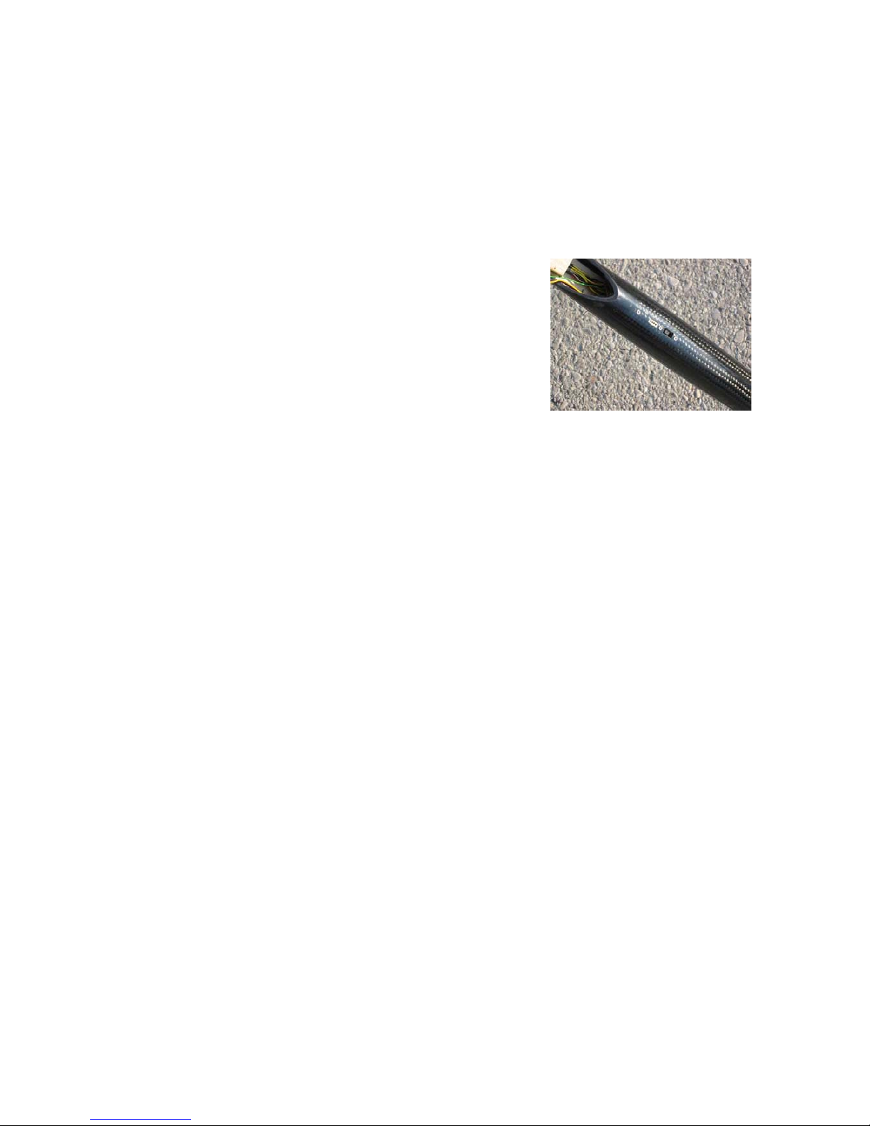
Erwin building instruction November 2006
Ready installed switch and socket on the outside of the
fuselage.
www.pcm.at 9

Erwin building instruction November 2006
8. Wing
The connection to the levers on the rudder goes crosswise
through the wing.
For easy putting in and out of the servos you can make a
mounting with two pieces of plywood.
Before you glue the lever to the rudder, mill a slit of about 10-
15mm in the control surface as shown on the picture to the
right.
Glue the smaller levers in the ailerons, the bigger ones in the
flaps.
www.pcm.at 10
Table of contents
Other Soaring USA Toy manuals






