Signature EZ Pro Jr. Indoor Installation guide

1
2
3
4
5
Part No.: 90060511
Revision No.: B
Date: July 2014
EZ PRO™Jr. Indoor Instructions Zone Chart
F equently Asked Questions
Please read before calling Customer Service.
Q.
A.
Does your system run
repeatedly?
Do NOT set a start time for
every zone. Only ONE start
time is necessary if the system
needs to run one time a day.
Q.
A.
ow do I delete a
start time?
Set the Start Time at
12:00. With the 12
blinking, touch the
ADJUST one time.
Q.
A.
Where do I leave
the LARGE dial?
Leave the dial on
TIME.
7
8
9

EZ Pro™Jr. Indoor
Installation and Programming Guide
For EZ ProTM Jr. Indoor models:
8204 8274
8206 8276
8209 8279
8212 8282
www.SignatureControlSystems.com

TABLE OF CONTENTS
Features 2
Installation 3-5
•Low Voltage Wiring 3
•Terminal Strip 3
•Connecting Master Valve or Pump-Start Relay 3
•Connecting Rain/Moisture Sensor 4
•Connecting Battery & Starting Controller 4
•Connecting the Transformer 5
Programming the EZ Pro™Jr. 6-15
Programming Ins ruc ions
•Programming Overview 6
•Front Panel Layout 7-8
•Set Time of Day 9
•Set Today's Date and Current Day of the Week 9
•Select Zones and Set Their Run Times 9
•Set Start Times 10
•Start Time Stacking 10
•Set % Water Budget 10
Programming Ins ruc ions - Program Mode
•Set Water Budget by Month (Advanced feature) 11
•Set the Watering Schedule 11-12
•Set Water Days Scheduling Option 12
•Set Odd/Even Day Scheduling Option 13
•Set Interval Scheduling Option 13
•Set Event Day Scheduling Option 14
•Program Review 14
•Set Master Valve or Pump Delay 14
Programming Ins ruc ions - Au o Mode
•Set the Rain Sensor Bypass 15
Programming Ins ruc ions - Off Mode
•Turning the Controller Off 15
Advanced Features 16-17
•Run a Zone Manually 16
•Run a Program Cycle Manually 17
Technical Data/Specifications 18-20
Troubleshooting/Service 21
FCC Rules 22

2
FEATURES
• Programmable delay between zones
• Three independent programs
• Three start times per program (9 total starts)
• Stacking start times
• Three scheduling options to suit the needs of plant material or to comply
with watering restrictions (days of the week, 1-30 day interval, true odd/even)
• Event days programming per program
• Rain Sensor bypass option
• Leap year compatible-automatically includes Feb 29th every four years
• Water budget option reduces or increases watering 0-200 percent
• Advanced water budget to set water budget for each month of the year
• Two test cycles (Manual with ManualAdvance feature and Cycle)
• Programmable run times from one minute to 1 hour 59 minutes
• Poly-fuse self resetting circuit protection

3
INSTALLATION INSTRUCTIONS
The EZ Pro™Jr. Indoor 8200 Series can be easily mounted indoors. Find a
location near a 120V receptacle (230/240V for 8274, 8276, and 8279 models).
Install the EZ Pro™Jr. Indoor near eye level if possible. Install the top screw in
the wall and adjust the depth for a snug fit when the controller is suspended
on the screw. Remove the wiring skirt and suspend the controller on the first
mounting screw and insert and tighten the second screw through the lower hole
provided in the case (pre-drilled or anchors as necessary).
Low Voltage Wiring
Low voltage output cables should be enclosed in conduit affixed near the
controller. (For field connection, AC wires must have an insulation rated at
75° C minimum). Conduit should be secured near the case (follow local codes).
Field wiring is best accomplished with the AC disconnected from the unit.
Terminal Strip
All zone, pump and sensor wire connections made inside the EZ Pro™Jr. Indoor
utilize screw type connectors that require a small screwdriver. The terminal
strips in the controller accept 12 AWG (2.1mm) wire or smaller. (See figure 1)
Connecting aster Valve or Pump-Start Relay
The EZ Pro™Jr. Indoor is equipped with a shared circuit to operate either a
pumpstart relay or a master valve. Connect one wire from the pump-start relay
to COM (common) on terminal strip, the other to PMP/MV (pump/master valve)
on the terminal strip. Refer to the pump-start relay manufacturer’s instructions
for specific installation details. (See figure 1)

INSTALLATION INSTRUCTIONS
Connecting Rain/ oisture Sensor
The EZ Pro™Jr. Indoor is equipped to operate a sensor with normally-closed
leads. To install a sensor, remove the factory-installed jumper wire from the
sensor connector on the terminal strip and insert the sensor wires. Refer to the
sensor manufacturer’s instructions for specific installation details. (See figure 1)
If a sensor has suspended watering, the sensor indicator segment will appear
on the LCD. The symbol will go off when the sensor has dried out. The
EZ Pro™Jr. Indoor will resume operation based on the selected program.
NOTE: anual operations will ignore the rain sensor
Connecting the Batteries and Starting the Controller
Remove the wiring skirt. Insert two new AA Alkaline (LR6 in Europe) batteries
into the battery clips in the pocket directly above the terminal strip. The AA
batteries enable the EZ Pro™Jr. Indoor to be programmed without AC power
and maintain the programs and real time clock in the event of a power outage.
If the batteries are not installed, the controller will lose real time and programs
in the event of a power outage. The batteries should be replaced every five years,
or when low battery symbol appears. Replace the batteries while the unit is AC
Powered to prevent loss of clock and settings. (See figure 1)
4

INSTALLATION INSTRUCTIONS
Connecting the Transformer
120 VAC in United States, Canada and Mexico; 230 VAC in Europe, and
240 VAC in Australia and South Africa
NOTE: Refer to and follow local codes if different from these instructions.
CAUTION: Disconnect 120V (230/240V for 8274, 8276, 8279 models) power
Connect the AC Power connector from the transformer to the plug provided on
the left side of the terminal strips and route the cable through the slot provided
in the case.
Attach the wiring skirt to the unit.
Plug the AC power adaptor into the nearest receptacle.
5
Power
Connector
Rain Sensor
Hot Spot Common
Pump/ aster Valve Zone Wiring
AA Battery
Compartment
FIGURE 1

PROGRAMMING INSTRUCTIONS
Programming Overview
The EZ Pro™Jr. Indoor can be programmed under AC power or powered from
the two AA alkaline batteries. Before programming the EZ Pro™Jr. Indoor, it
may be helpful to become familiar with some general programming guidelines:
• If a segment(s) on the LCD is flashing, it means that it can be changed
by the user.
• When using keys, hold the button three seconds to start a fast scroll.
• Be sure the appropriate program letter is displayed when you are
programming; program changes are specific to the program letter
displayed on the LCD.
• There is no “ENTER” key. Key-presses and dial settings are stored
automatically for you.
• If you make a programming change while a program is running, the
program terminates immediately. The new program starts at the next
start time scheduled.
• When not running, the controller displays the current time and the current day.
• During manual operations, there is a 5-second delay before the operation
begins. During this time, you can change your settings. Each time you
make a change, the delay resets to 5 seconds.
• MANUAL and CYCLE procedures only operate with the Program dial set
in the AUTO position.
• After a test procedure runs, the controller reverts back to the AUTO
procedure and runs the next program scheduled.
• The test procedures ignore the sensor connection; this allows
you to water or run your program even if the sensor has
suspended operation.
• To clear all programs and start over, press and hold SELECT ‘–’ and
ADJUST ‘–’ for three seconds
• Only one start time is needed per cycle. All programmed zones will
run sequentially.
• All three programs are independent and will run if programmed
regardless of dial position.
6

PROGRAMMING INSTRUCTIONS
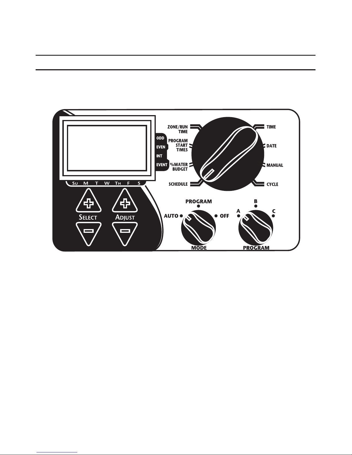
Front Panel Layout
Looking at the front panel (See figure 3), you see a large LCD, 4 rubber
buttons, one large rotary dial, and two small rotary dials. The rubber buttons
are marked SELECT and ADJUST and are the core of Signature’s exclusive
SELECT&ADJUST programming. The keys are identified with ‘+’ or ‘–’ for
increasing or decreasing the segment you’re working on.
SELECT&ADJUST works on the principle that you first SELECT what you want
to set, and ADJUST the variables of what you selected. For example, if you
want a run time of 10 minutes on zone 5, you would use the SELECT keys to
select zone 5 and, once on zone 5, you would use the ADJUST keys to set the
run time to 10 minutes.
There are instances when only SELECT or only ADJUST are required.
They will be explained in this guide where appropriate.
7
PROGRAMMING INSTRUCTIONS
FIGURE 3
NOTE: The ODE dial must be in the PROGRA position.
NOTE: Every time the ‘+’ or ‘–’ key is pressed, the display will increase
or decrease one unit. Hold the ‘+’ or ‘–’ key for three seconds to
initiate a fast scroll.
NOTE: Please refer to the Technical Data section for an explanation of the
LCD segments.
8
This manual suits for next models
1
Table of contents
Other Signature Controllers manuals


Popular Controllers manuals by other brands

Digiplex
Digiplex DGP-848 Programming guide

YASKAWA
YASKAWA SGM series user manual

Sinope
Sinope Calypso RM3500ZB installation guide

Isimet
Isimet DLA Series Style 2 Installation, Operations, Start-up and Maintenance Instructions

LSIS
LSIS sv-ip5a user manual

Rockwell Automation
Rockwell Automation 1769-L31 installation instructions


