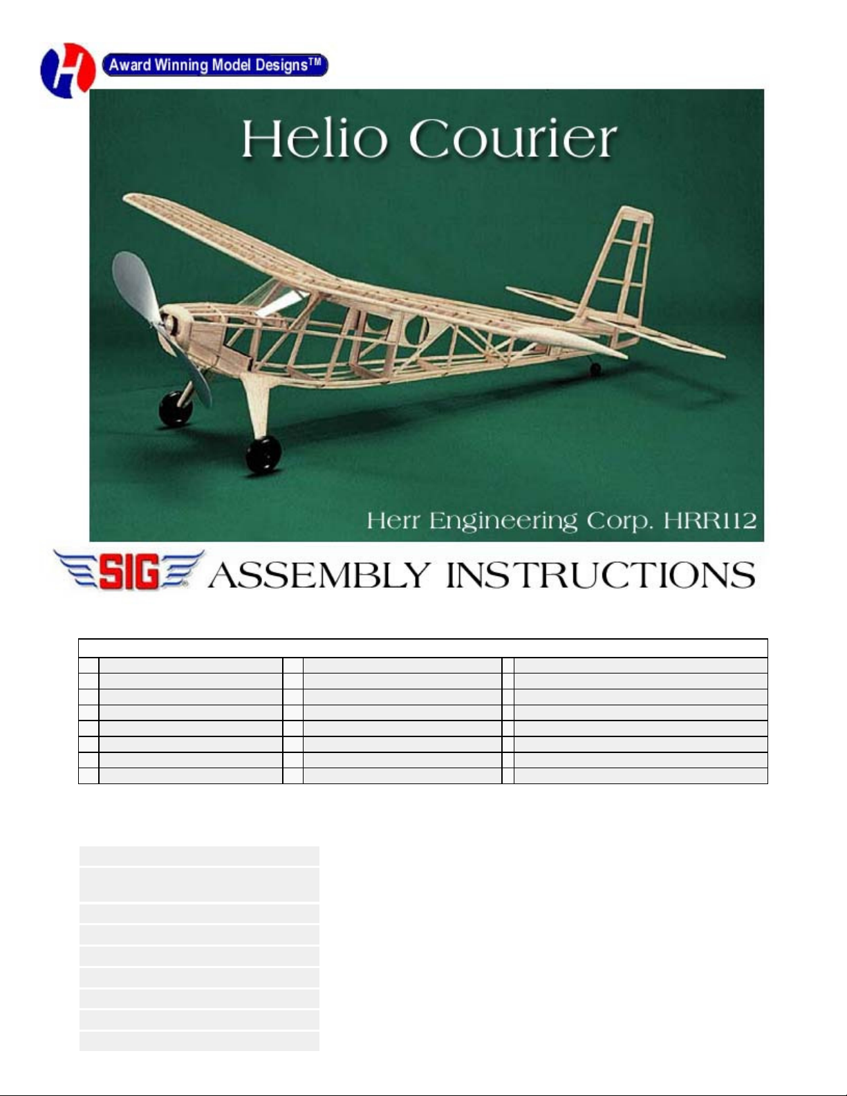
SIG Helio Courier User manual

Your kit contains the following parts. Please check your kit for any missing or damaged parts before starting construction.
COMPLETE KIT PARTS LIST
1 Plan Sheet 1 Decal Sheet 2 White Tissue
1 Red Tissue 1 1/16"x12" Landing Gear Wire 3 6"x3 1/4" Windshield Plastic
16 1/16" sq x18" Balsa Strip 18 3/32" sq x18" Balsa Strip 2 1/8" sq x18" Balsa Strip
6 3/32"x1/4"x18" Balsa Strip 1 3/16"x1 3/4" Birch Dowel 2 1/2"x3/4"x4 3/4" balsa wing tip block
1 Tail Wheel Assembly 1 Instruction Manual 1 Molded Plastic Propeller
1 Propeller Shaft 2 Brass Washer 1 Nylon Propeller Bearing
2 Plastic Wheels 1 3/16"x60" Rubber Strip 2 Plastic Wheel Retainers
5 Laser Cut Sheets
Tools and Building Supplies
You will need the following items to assemble this model. You must read and follow all of the manufactures
instructions provided with these items!
-Glue CA, White Glue, Sigment or Ambroid all work well.
-Cutting Tools A hobby knife with a #11 blade is used for general cutting. A single edge
razor blade is also a useful cutting tool.
-Clear Dope, Thinner & paint brush
-320 and 400 grit sandpaper
-Straight Pins
-Wax Paper
-Needle nose pliers
-1/4" Drill Bit
-Building Board

.
The first thing that you need to do is to identify and mark the part numbers on the laser cut parts using the drawings on the
following pages as a guide.
It is possible that several of the laser cut parts may not be completely cut through. If this is the case you can free the part from
the sheet quickly using an X-acto knife.
NOTE: The slight discoloration on the edges of the laser cut parts may be removed by lightly sanding the edges with 400 grit
sandpaper.

.
Building the Tail Surfaces
1.
Always cover the plan with wax paper before building any parts over the plan. This will prevent the parts from sticking to the
plan.
2.
Build the rudder over the plan using parts R-1, R-2 and R-3. The remainder of the structure is made from 3/32" sq. balsa
strip and 3/32" x 1/4" balsa strip as shown on the plan.
3.
Build the stabilizer over using parts S-1 and S-
2. The remainder of the structure is made from 3/32" sq. balsa strip and 3/32"
x 1/4" balsa strip as shown on the plan.
4.
When the glue is dry, remove the rudder and stabilizer from the plan and sand the surfaces smooth and round the edges.
Test fit the stabilizer into the slot in the rudder. Now set these parts aside until needed later.
Building the Wing
5.
The wing is built in one piece. The first step is to pin the main spars W-1 to the plan and join them using part W-2. This will
also establish the proper dihedral angle.
6.
Pin the center section of the joined spar into position over the plan. Cut and pin into position the 3/32" x 1/4" trailing edge for
the center section.
7.
Glue rib W-3 and the adjacent two W-4 ribs to the lower spar and the center section trailing edge.
8.
Cut the 3/32" sq. top spar, the 1/16" sq. strips and the 1/8" sq. leading edge to length and glue into position on the wing
center section.
9.
Remove the pins from the wing center section and rotate the wing so that the right bottom spar is in full contact with the
plan. PIace this spar in the proper position on the plan and pin the spar to the plan.
10.
Cut the 3/32" x 1/4" trailing edge to length and pin it into position over the right wing plan.
11.
Glue seven W
-
4 ribs into position to the bottom right spar and the trailing edge.
12.
Glue the 3/32" sq. top spar into position.
13.
Glue the 1/8" sq. leading edge into position. Glue the 1/16" sq. strips into the notches in the top front of the ribs.
14.
Remove the pins from the wing assembly and rotate it so
that the left bottom spar is in the proper position over the plan and
pin the wing into position.
15.
Build the left wing panel as you did the right.
16.
Remove the wing from the plan and glue the wing tip blocks into position.
17.
Sand the wing smooth all over. Sand the wing tips to shape, taper the trailing edges and round the leading edges.
18.
Set the wing aside until needed later.
Building the Fuselage
19.
Build the two fuselage side frames over the main plan using parts F-1, F-2, F-3 and F-4. The remaining pieces of the side
frames are made from 3/32" sq. balsa strips.
20.
Glue the 3/32" sq. strips to the rear face of formers F
-
5 and F
-
6 as shown on the plan.
21.
Position Formers F-5 and F-6 onto one of the side frames. Make sure that they are 90 degrees to the side frames and glue
them into position.
22.
Glue the opposite side frame to formers F-5 and F-6.

.
23. Crack the side frames just behind former F-6 at the locations shown on the plan. Pull the rear of the fuselage together and
carefully glue together making sure that the aft fuselage is straight and true.
24.
Glue former F-7 into position at the front of the fuselage.
25.
Glue formers F-8T and F-8B into position.
26.
Glue F-9 into position on the fuselage as shown on the plan.
27.
Glue the two 3/32" sq. cross pieces into position between the fuselage sides in the upper cabin area.
28.
Glue F-10 into position. Glue two 3/32" sq. reinforcements inside the side frames between F-10 and the cross piece at the
top of the cabin.
29.
Glue F
-
11T and F
-
11B into position.
3O.
Glue F
-
12T and F
-
12B into position.
31.
Glue F
-
13 into position.
32.
Bend the landing gear wire to the shape shown on the plan.
33.
Glue the landing gear wire into position on the front of F
-
5.
34.
Glue F
-
5B and F
-
5C into position trapping the landing wire into place.
35.
Glue the 3/32" sq. strips into position on the top of the nose between F
-
7 and F
-
9.
36.
Glue the 3/32" sq. strips into position on the bottom of the nose between F
-
7 and F
-
5B.
37.
Glue the 1/16" sq. strips into position on the bottom rear fuselage between F
-
5 and the aft end.
38.
Glue the rudder to the rear of the fuselage. The forward end of R-1 fits into the slot in F-13. Use care to make sure that the
rudder is straight and aligned properly.
39.
Glue the 1/16" sq. strips to the top rear of the fuselage between F
-
6 and the tail.
40.
Glue the nose block pieces NB
-
1, NB
-
2, NB
-
3 and the two NB
-
4's together.
41.
Fit the nose block to the front of the model. Now sand the nose block to shape. Also, sand the entire fuselage smooth at this
time.
42.
Drill the nose block for the 1/4" dia. nylon nose bearing. Be careful to maintain the proper amount of right and down thrust.
43.
Laminate two pairs of parts LG. Sand them to a streamline cross section and test fit into position on top of the landing gear
wire. The top edge of these parts will need to be beveled to fit flush with the side of the fuselage.
Covering The Model
44.
Sand the entire model with 320 grit sandpaper.
45.
Coat the outside edges of all parts with 2 coats of clear dope.
46.
Attach the tissue to the model with clear dope mixed 50/50 with thinner.
47.
Lightly mist the model with water to shrink the dope.
48.
Apply 2 coats of thinned clear dope to the entire model.
49.
Attach colored trim tissue with clear dope.

.
50.
Apply the decal numbers to the model.
51.
Draw additional detail onto the model with a waterproof marker.
Final Assembly
52.
Glue the wing to the model.
53.
Cut P-1 from the plan and glue it to the top of the wing at the center section trailing edge.
54.
Cut. fit and glue the 1/16" sq. strips into position from the front edge of P
-
1 to F
-
6.
55.
Cover this area with tissue as you did the rest of the model.
56.
Glue the stabilizer into position making sure that it is straight and aligned properly.
57.
Cut, fit and glue the side windows into position.
58.
Cut the windshield to the shape shown on the plans and fit it to the model. When the proper fit has been achieved, glue the
windshield to the model.
57.
Glue the landing gear fairings to the model.
58.
Assemble the plastic wheels and secure them to the model with the plastic wheel retainers.
59.
Assemble the tail wheel and glue to the fuselage.
60.
Assemble the propeller. Glue this assembly into the removable nose block.
61.
Tie the rubber motor and install it along with the nose block. Retain the motor at the rear of the fuselage with the 3/16"
dowel provided.
62.
Balance the model at the position shown on the plan.
63.
Your Helio Courier is now complete.
Beginners Note
These instructions were written assuming that the builder has previous building experience. If this is your flrst model then
we recommend that you purchase a copy of the following book:
Rubber Powered Model Airplanes By: Don Ross
This excellent book covers basic building and flying procedures and provides valuable information about all aspects of
building and flying rubber powered model airplanes.
Safety Rules
1. Fly your model in a large open area that is free of obstructions, people or their property.
2. Do not fly your model in the vicinity of power lines, trees, streets or buildings.
3. Never try to retrieve any model stuck in power lines, in trees or on a roof or other high place.
Never run into the street to retrieve your model.
4. Position yourself at least 150' from spectators before launching model.
5. Never launch model directly at another person or other object.
6. Never stick your fingers into a spinning propeller. Do not try to stop a spinning propeller with
your hand or fingers. Never stick any object into a spinning propeller.
7. Fly your model only on calm days. Do not fly when the wind is blowing.
8. Get proper permission before retrieving your model from private property.

.
Your First Flights
1.
Make sure that all flying surfaces are straight and warp free.
2.
Wind the motor about 100 turns.
3.
Point the nose of the model into any gentle breeze that may be blowing.
4.
Release the propeller and after it starts turning gently toss the model aiming the nose at a point on the ground 100' in front
of you. Adjust the model to circle while gradually increasing the number of turns in the motor. Adjustments can be made by
gently bending the tail surfaces and wing trailing edge.
5.
A properly trimmed model will circle to the left while climbing under power, level out as the power runs down and transitions
into a right hand circling glide.
WARRANTY
Herr Engineering Corp. guarantees this kit to be free from defects in both materials and workmanship at the time of purchase.
This warranty does not cover any component damaged buy use or modification. In no case shall Herr Engineering
Corporation's liability exceed the original cost of the purchased kit. Further Herr Engineering Corp. reserves the right to
change or modify this warranty without notice.
In that Herr Engineering Corporation has no control over the assembly or use, no liability shall be assumed or accepted for
any damage resulting from the use by the user during construction of the kit or the use of the final user assembled product.
By the act of building this kit and/or using the final user assembled product, the user accepts all liability.
If the buyer and/or user is not prepared to accept all of the liability associated with this product, he is advised to immediately
return this kit in new and unused condition to the place of purchase for a full refund.
©
Copyright SIG Mfg. Co., Inc.
SIG MFG. CO., INC............Montezuma, Iowa 50171
-
0520
LIMIT OF LIABILITY:
In use of our products, Sig Mfg. Co.'s only obligation shall be to replace such quantity of the product proven to be defective.
User shall determine the suitability of the product for his or her intended use and shall assume all risk and liability in connection
therewith.
Table of contents
Other SIG Toy manuals

SIG
SIG Extra 300XS User manual

SIG
SIG King Kobra Instruction Manual

SIG
SIG FOUR-STAR 40 ARF User manual

SIG
SIG CAP 231EX User manual

SIG
SIG Ryan S-T Datasheet

SIG
SIG Kadet Senior User manual

SIG
SIG Four-Star 120 User manual

SIG
SIG KADET EP-42B User manual

SIG
SIG Tiger SIGFF22 Classic Series User manual

SIG
SIG Wonder Instruction Manual

SIG
SIG WACO SRE SIGRC101ARF User manual

SIG
SIG DORN IER Do 217 User manual

SIG
SIG KADET EP-42 User manual

SIG
SIG MESSERSCHMITT Bf-109 User manual

SIG
SIG Sigrc47 Instruction Manual

SIG
SIG Gee Bee R-2 User manual

SIG
SIG 4-STAR 60 Instruction Manual

SIG
SIG SIGRC69 HOG BIPE User manual

SIG
SIG RASCAL EP-49 User manual

SIG
SIG HERR FAIRCHILD 24 User manual