Shuttle TNT User manual

Page 1
TNT

Page 1
Congratulations on the purchase of your new Shuttle TNT. Shuttle equipment has been trusted by physical therapists and
sports training facilities around the globe for almost half a century. It is our mission to deliver the finest quality exercise
devices with superior customer service. We welcome you as a valued customer.
For your safety it is crucial that you read this manual thoroughly and understand the equipment before use. If you have any
questions about your Shuttle TNT you can give us a call at +1 (800)-334-5633, email us at
[email protected], or chat with us via live chat at www.shuttlesystems.com (Monday-Friday, 8 am to 5
pm Pacific Time).
WELCOME TO THE FAM

IMPORTANT SAFETY INFORMATION ..…………………………………………………………….…………. 1
PERSONAL SAFETY ……….……………………………………………………………………….……………. 1
SPECIFICATIONS ………………………………….………………………………………………..…..……….. 2
IDENTIFICATION OF THE MANUFACTURER …………………………………………………………..……. 3
ASSEMBLY OF THE TNT ………………………………………………………..……………………….……… 4
- REMOVING THE CARRIAGE………………………………………………….….…..5
- ATTACHING THE HEAD-END STAND………………………………………..…..…6
- ATTACHING THE KICKPLATE STRUCTURE………………………………….……..7
- INSTALLING THE SEAT………………………..………………….…………………..9
- INSERTING THE CARRIAGE…………………………………………………..…….11
- ATTACHING THE KICKPLATE BOARD………………………………………..……12
- ATTACHING THE LOW PROFILE HEADREST……………….….….……..….……12
- ATTACHING THE TOWERS (TNT WITH TOWERS ONLY)………..…….…….…..14
- ATTACHING THE PULLEYS (TNT WITH TOWERS ONLY).……….………….……15
USING THE PRODUCT ………………………………………………………………………….………….….. 16
MAINTENANCE AND CARE ……………………………………………………………………….….……… 18
WARRANTY ………………………………………………………………………………………….………….. 19
SUPPORT ………………………………………………………………..……………………..………….…….. 20
TABLE OF CONTENTS

Page 1
Read all safety information before operating the TNT. It is the owner’s responsibility to ensure that users are aware of
all warnings and precautions.
Please read all instructions before using the product. These instructions were written to ensure the safety of the user and to
protect the product.
You should always consult with a physician before beginning a new fitness plan.You are advised to investigate and inform
yourself about any health related actions and choices you make.
Use caution when mounting and dismounting.
Do not allow children to have unsupervised access to the product.
Keep pets away from the TNT at all times.
Perform regular maintenance for optimal performance and longevity. To ensure safety, the TNT must be checked for wear
and damage on a regular basis.
Replace any damaged or worn parts immediately. Do not use the TNT until the repair is performed.
Use only original parts from the manufacturer. Changes or modifications to this unit not expressly approved by Shuttle
Systems could void the warranty.
The TNT is for indoor use only. Do not store the TNT outdoors, near water, or at high humidity levels.
Fully assemble the product before using it. Check the product before each use. Do not continue to use the product if it is
not working properly.
Use of this product is subject to medical examination to assess your suitability to the type of workout exercise you intend to
perform, and in compliance with the conditions for use laid down by Shuttle Systems.
Persons suffering from certain physical conditions may only use the product under the strict supervision of a doctor with
specific qualifications.
Before starting any workout, make sure your position on the product is correct, paying attention to any components that
may obstruct use.
Plan the workout according to your physical characteristics and state of health, beginning with less demanding workloads.
Do not overexert yourself or work to exhaustion. Incorrect or excessive exercise may cause physical harm or sudden death.
If you feel any pain or abnormal symptoms, stop your workout immediately and consult your physician.
Wear proper workout clothing and shoes during training; do not wear loose clothing. Tie long hair back. Keep hands,
shoelaces, garments, and accessories away from moving parts. Do not insert objects into openings on the equipment.
When using the TNT, other people must remain at a safe distance.
Do not use the product when children or pets are present.
The person in charge of the gym must explain proper and improper use of the equipment to users.
Assemble and use the product only on a solid and flat surface.
Keep the product in good working condition. If you see signs of wear, contact Shuttle Technical Support Service.
Do not attempt any maintenance work on the product other than the operations described in the user manual.
IMPORTANT SAFETY INFORMATION
PERSONAL SAFETY
Page 2
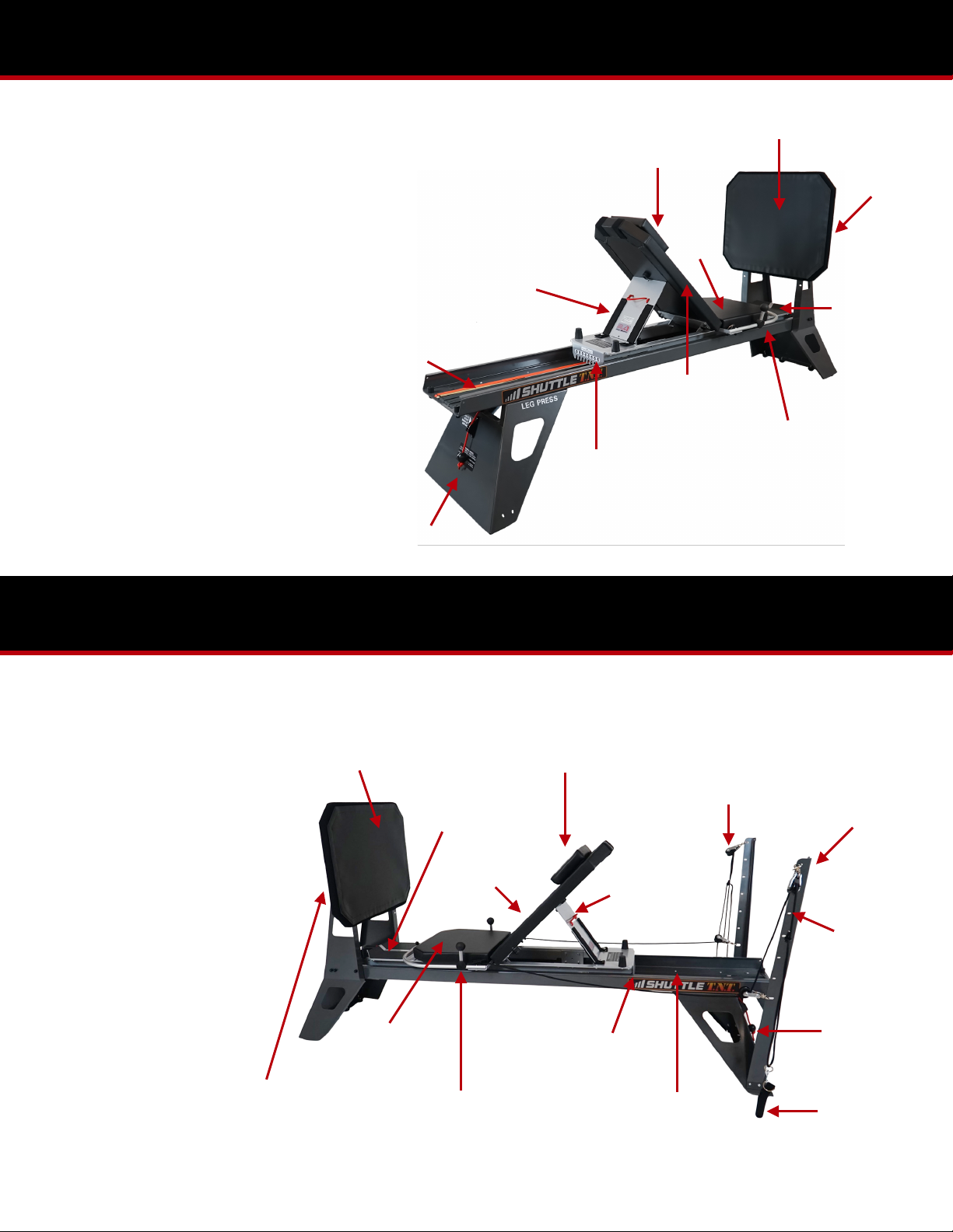
Dimensions: 30”W x 105”L
Floor Space Required: 3’W x 10’L
Carriage Capacity: 450 lbs
Max Resistance:
TNT: 6-250 lbs*
Total Elasticords:
TNT: (8) Elasticords Total;
(1) 6 lb Elasticord,
(1) 12 lb Elasticord
(6) 25 lb Elasticords
KICKPLATE
HEADREST
BACKREST
ELASTICORDS
ROM HANDLE
KNURLED
KNOBS
SLOTTED
PLATE
SPECIFICATIONS (TNT WITH TOWERS)
ADJUSTABLE
PLATE
* Elasticords are rated starting
resistance, but will gain
resistance up to 40% in
extension
HEADREST
BACKREST
ELASTICORDS
ROM
CONTROL
ROPE
SLOTTED
PLATE
ADJUSTABLE
PLATE
ADJUSTABLE
HANDLEBARS
KICKPLATE
FOOTREST
SEAT
TOWERS
ADJUSTABLE
PULLEYS
PULLEY
HANDLES
KNURLED
KNOBS
TOWER
SLOTS
Dimensions: 30”W x 105”L
Floor Space Required: 3’W x
10’L
Carriage Capacity: 450 lbs
Max Resistance:
TNT: 6-250 lbs*
Total Elasticords:
TNT: (8) Elasticords Total;
(1) 6 lb Elasticord,
(1) 12 lb Elasticord
(6) 25 lb Elasticords
* Elasticords are rated starting
resistance, but will gain
resistance up to 40% in
extension
SEAT
FOOTREST
ADJUSTABLE
HANDLEBARS
SPECIFICATIONS
SPECIFICATIONS (TNT WITH TOWERS)
Page 3
C
A
B
D
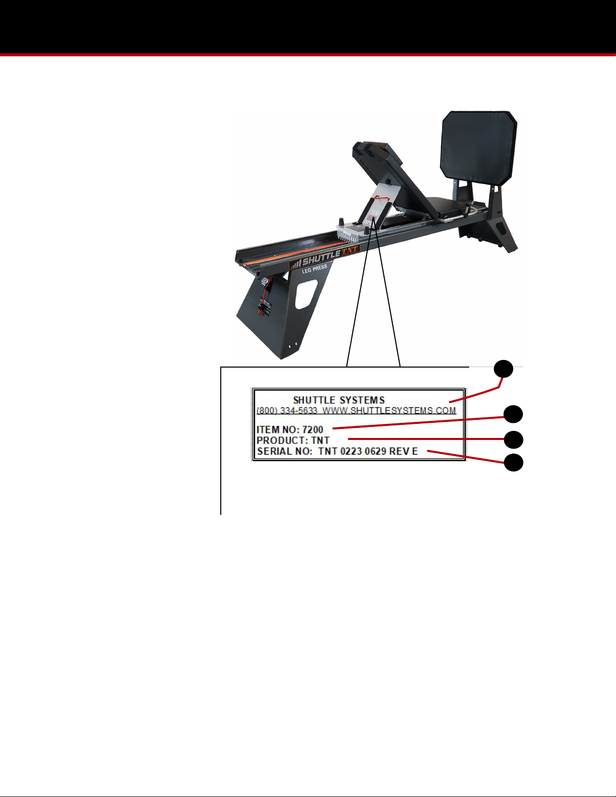
A - Manufacturer’s name and contact
B - Item number
C - Description of product
D - Serial number
IDENTIFICATION OF MANUFACTURER
Page 4
Assembly of the TNT requires two people.
Tools Needed: 7/16 inch socket or combination wrench, 1/2 inch socket of combination wrench.
Keep in mind that the following images in Steps 1-7 pertain to the TNT without towers, if you bought the TNT with towers
your parts may appear slightly different than those in the included images but the required steps remain the same.
The TNT will come in two boxes:
1. TNT Rails and Carriage
- TNT Rails
- Carriage
- Headrest
- Parts Bag
- Towers (only if ordered)
- Accessories (only if ordered)
2. TNT Stands
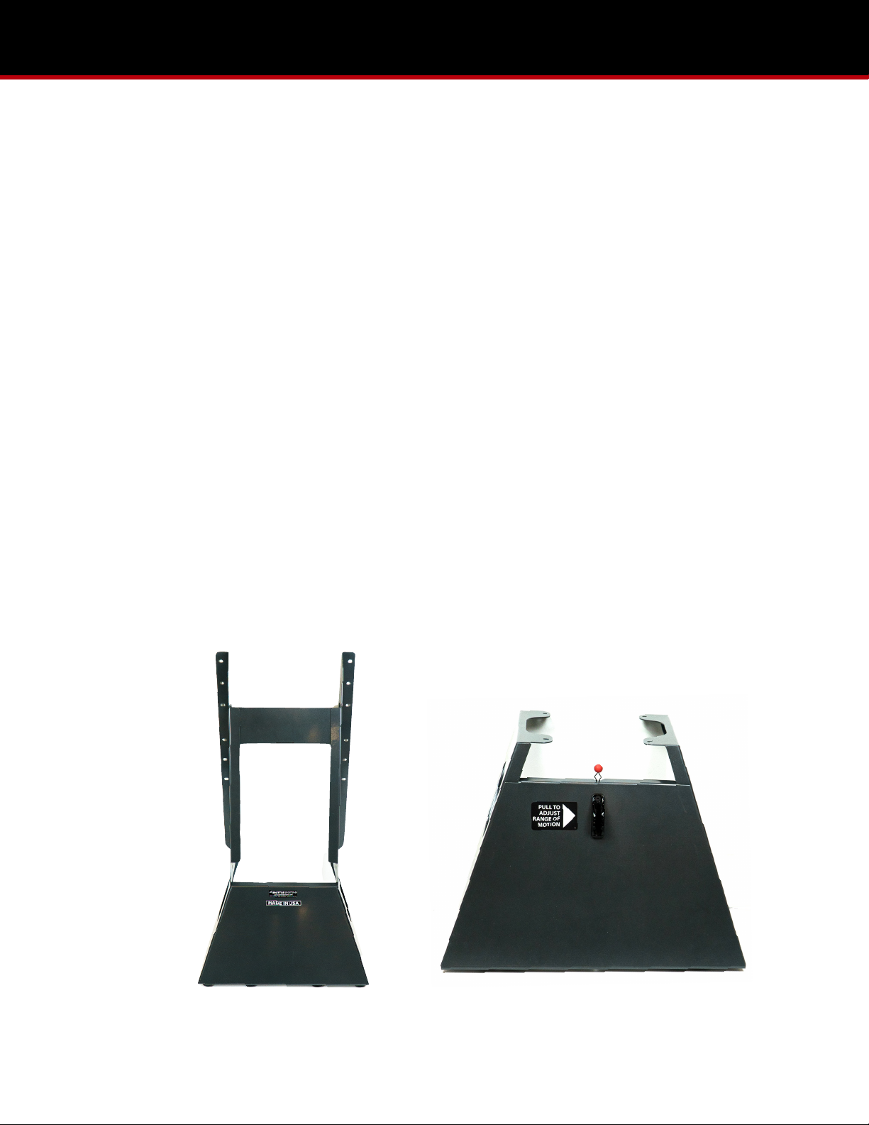
- Kickplate Structure
- Head-End Stand
- Kickplate Board
Head-End Stand
(Head-End)
Kickplate Structure
(Foot-End)
It is important to become familiar with the expressions “Foot-End and Head-End” as they indicate orientation for the
various steps and structures.
ASSEMBLY OF THE TNT
Page 5
REMOVING THE CARRIAGE
STEP 1
ITEMS REQUIRED
Carriage
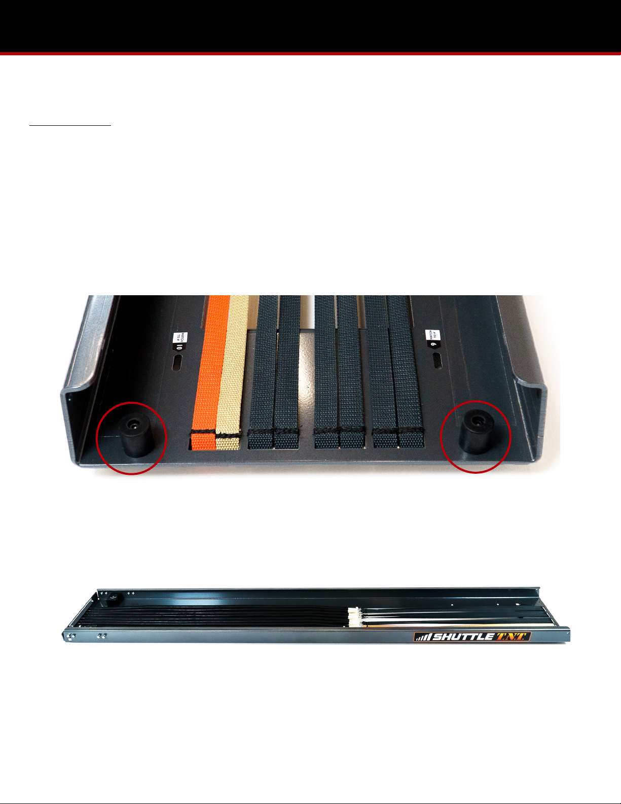
1. Remove the two rubber bumpers at the head-end of the TNT rails. Set them aside for Step 5. (Pic 1.1)
2. The carriage can now be removed by pulling it out through the head-end of the rails. Gently set the carriage to the side
for now. (Pic 1.2)
1.1
1.2
ASSEMBLY OF THE TNT (STEP 1)

Page 6
ATTACHING THE HEAD-END STAND
STEP 2
ITEMS REQUIRED
TNT Rails
Head-End Stand
1. Flip the rails upside down, exposing four lock nuts at the head-end of the TNT rails. Remove the four bolts (two on each
side) from the rails. (Pic 2.1)
2. Align the holes of the head-end stand with the now exposed bolt holes on the TNT rails. The head-end stand should be
flipped upside down so the rubber feet are facing up. (Pic 2.2)
3. From the underside of the TNT rails, insert the four bolts up into and through the head-end stand. Hand tighten the lock
nuts. It is important to make sure the lock nuts are against the head-end stand as they will interfere with the carriage if
they are along the TNT rails. (Pic 2.3)
2.1
2.2
2.3
ASSEMBLY OF THE TNT (STEP 2)

Page 7
ATTACHING THE KICKPLATE STRUCTURE
STEP 3
ITEMS REQUIRED
Kickplate Structure
Parts Bag
1. Flip the TNT rails and head-end stand over with the foot-end resting on the ground. (Pic 3.1)
2. Remove the eight bolts (four on each side) at the foot-end of the TNT rails. (Pic 3.2)
3. Position the foot-end of the TNT rails to the inside of the kickplate structure. Align the holes and insert the eight bolts
into the rails and through the kickplate structure. (Pic 3.3)
4. Tighten down all bolts at the kickplate structure and head-end stand. (Pic 3.4)
5. Place the eight nut caps (four on each side) from the parts bag, onto the eight lock nuts at the kickplate structure.
Images on next page
ASSEMBLY OF THE TNT (STEP 3)
Other manuals for TNT
2
Table of contents
Other Shuttle Fitness Equipment manuals

Shuttle
Shuttle MVP Elite Plus User manual

Shuttle
Shuttle MVP User manual

Shuttle
Shuttle BALANCE User manual

Shuttle
Shuttle MVP User manual

Shuttle
Shuttle TNT User manual

Shuttle
Shuttle Z0-2734 User manual

Shuttle
Shuttle MiniPress User manual

Shuttle
Shuttle Ultimate User manual

Shuttle
Shuttle BALANCE User manual

Shuttle
Shuttle BALANCE User manual