Sanus BLF328 User manual

BLF328
INSTRUCTION MANUAL
Texto en español, página 14
GET IT
RIGHT
THE FIRST TIME
Follow this step-by-step
instruction manual to
speed up your installation.
WE’RE HERE TO HELP
Our US-based install experts
are standing by to help.
Call us at:
800-359-5520
Or, chat at:
SANUS.com/chatSP
Get it right the first time.
HeightFinder™ shows you
where to drill.
Check it out at:
SANUS.com/1172
Want to watch a video that
shows how easy this DIY
project will be?
Watch it now at:
SANUS.com/2783

2
125 lbs.
(56.6 kg)
IMPORTANT SAFETY INSTRUCTIONS – PLEASE READ MANUAL PRIOR TO USE – SAVE THESE INSTRUC-
TIONS
Please read through these instructions completely to be sure you’re comfortable with this easy install process.
Check your TV owner’s manual to see if there are any special requirements for mounting your TV.
If you do not understand these instructions or have doubts about the safety of the installation, assembly or use of this product,
contact Customer Service 1-800-359-5520.
CAUTION: Avoid potential personal injuries and property damage!
●This product is designed ONLY to be installed into wood studs, solid concrete or concrete block.
— DO NOT INSTALL INTO DRYWALL ALONE — DRYWALL ALONE WILL NOT HOLD THE WEIGHT OF YOUR TV.
●This product is designed for INDOOR USE ONLY.
●The wall must be capable of supporting five times the weight of the TV and mount combined.
●Do not use this product for any purpose not explicitly specified by manufacturer.
●Manufacturer is not responsible for damage or injury caused by incorrect assembly or use.
TV Weight Limit
(including accessories)
DO NOT EXCEED
If your TV (including accessories) exceeds
this weight, this mount is NOT compatible.
Visit SANUS.com or call customer service to
find a compatible mount.
1-800-359-5520
Call Customer Service
1-800-359-5520
Tools Needed
Wall
Construction
ONLY install on
these acceptable
wall types. Drywall alone
will NOT hold
the weight of
your TV.
Unsure
wood studs Solid concrete or
concrete block
ACCEPTABLE ACCEPTABLE
Wood Stud Install
Concrete Install
Awl
Pencil Level Tape
Stud
Finder
ScrewdriverTape
Measure
7/32 in.
(5.5 mm)
Wood
Drill Bit
Electric
Drill
Hammer
1/2 in.
(13 mm)
Socket
Wrench
Drill Bit
3/8 in.
(10 mm)
Concrete
CAUTION:
DO NOT install
in drywall alone

3
Dimensions
7.87in
200mm
MIN
7.87in
200mm
MIN
15.75in
400mm
MAX
23.62in
600mm
MAX
14.55in
369.6mm
2.36in
60mm
21.83in
554.6mm
16.00in
406.4mm
18.72in
475.6mm
11.57in
293.8mm
9.27in
235.4mm
24.00in
609.6mm
.36in
9.1mm
33.68in
855.6mm
33.80in
858.6mm
17.69in
449.3mm
.22in
[5.6mm]
OFFSET
2.15in
54.6mm
28.00in
711.2mm
5 deg
15 deg
UP
DOWN
9.08in
230.8mm
8.60in
218.6mm
C
L
TV INTERFACE
WALL PLATE
TOP VIEW - EXTENDED
3-D
SIDE VIEW - EXTENDED
SIDE VIEW RETRACTED
TOP VIEW - RETRACTED
FULLY ASSEMBLED MOUNT
WALL IS ON RIGHTWALL IS ON RIGHT
57deg
WALL IS ON TOP
WALL IS ON TOP
57deg
SIMULATED 65"
FLAT SCREEN TV
TOP VIEW - EXTENDED
57deg
WA
57de
g
A
TED
65"
C
REEN T
V
BEFORE YOU BEGIN
Remove the stand
from your TV — if attached. Install any accessories
you may have purchased, if they
require TV removal prior to assembly.
The TV is removable for future
accessory purchases.
Soft clean surface
Protect the face
of your TV when laying it
down for installation.

4
03
06
06
02
02 01
01
Too Short Too Long Correct
M8 x 35mm
M8 x 16mm
22mm
M6 x 12mm M6 x 35mm
M8 x 50mm
2.5mm
5mm
M8 x 25mm
M5 x 10mm
STEP 1 Parts and Hardware
TV Screws
(qty. 4 each) [Only one size fits your TV] Washers
(qty. 4 each)
Spacers
[If necessary]
(qty. 4 each)
0302
01
M6/M8 M6/M8
M6
M8
(qty. 1)
04
(qty. 4)
05
(qty. 2)
06
TV Bracket Vertical
Interface Screw
TV Bracket
Horizontal
MOUNTING TABS
(ATTACHED)
MOUNTING TABS
M
Inset Holes Cables Rounded Back
Only one screw size fits your TV.
M6 M8 • Flat Back TV
[TV brackets
lay flat on your TV]
NO SPACER SPACER NEEDED
• Flat Back TV with
Extra Space Needed
[for deep inset holes
or cable interference]
• Rounded or
Irregular Back TV
[TV brackets NOT
resting flat on your TV]
A B
Use short TV screws 01 .
Spacers 03 not needed. Use long TV screws 01 and spacers 03 to
create extra space between the TV and TV bracket.
01
1.2 Select TV Screw Length and Spacers1.1 Select TV Screw Diameter
CAUTION: Verify adequate thread
engagement with your screw 01 , washer 02 ,
spacer 03 combination AND TV bracket 06 .
— Too short will not hold your TV.
— Too long will damage your TV.
Attach TV Bracket to TV
STEP 1
WARNING: This product contains small items that could be a choking hazard if swallowed. Before starting assembly, verify all parts are included
and undamaged. If any parts are missing or damaged, do not return the damaged item to your dealer; contact Customer Service. Never use damaged parts!
NOTE: Not all hardware included will be used.
RELEASE CORD
(ATTACHED)
RELEASE CORD
(ATTACHED)
R
NOTE: If your TV
included inset spacers
or adapters, use them
UNDER the mount
hardware.

5
1.3 Attach TV Brackets to Your TV
W
Adjust mounting tabs M on TV brackets 06 to match the width W
of your TV's mounting hole pattern.
400 mm position illustrated
2ADJUST TO WIDTH W
Measure the WIDTH and HEIGHT of your TV's mounting hole pattern.
1MEASURE
inch dimensions are approximate
W
H
06
M
M
inches cm mm
410 100
7⅞20 200
11 ¾ 30 300
15 ¾ 40 400
19 ¾ 50 500
23 ¾ 60 600
W
H
mm
mm
inches
cm
mm
4
10
100
For height 300 mm or less For height greater than 300 mm
For hole pattern height H greater than 300 mm, align horizontal TV
brackets 06 with mounting tabs M to the outside.
For hole pattern height H 300 mm and less, align horizontal TV
brackets 06 with mounting tabs M to the inside.
3a ASSEMBLE FOR HEIGHT H3b ASSEMBLE FOR HEIGHT H
≤ 300 mm > 300 mm
04
04
06
06
06 06
MM

6
TV bracket 04 must be centered on your TV, but can be offset up or
down to avoid cable interference.
5CENTER
Adjust TV brackets 06 to align with your TV hole pattern. Install using the
screw 01 /washer 02 /spacer 03 combination you selected for your TV.
04
06
4LOOSELY ASSEMBLE
4X
01
02 02
03
01
NO SPACER SPACER NEEDED
A B
06
06
Secure the TV brackets using four interface screws 05 , starting with
the TOP two screws in the notches shown.
6SECURE ASSEMBLY
2X
05
2X
05
05
2X
0505
Securely tighten the screws from STEP 4 and STEP 6.
7TIGHTEN ALL SCREWS
8X
01
05
a
b

7
Fischer UX10 x 60R
5/16 in. x 3½ in.
09 x4
07 x1
08 x1
10
x4
Parts and Hardware for STEP 2
Lag Bolt
Wall Plate
Wall Plate
Template
Concrete Anchor
For concrete installations ONLY
CAUTION: Do not use in drywall or wood
Cover
(Attached)
P
Attach Wall Plate to Wall
STEP 2
WARNING: This product contains small items that could be a choking hazard if swallowed. Before starting assembly, verify all parts are
included and undamaged. If any parts are missing or damaged, do not return the damaged item to your dealer; contact Customer Service.
Never use damaged parts!
NOTE: Not all hardware included will be used.
For
CONCRETE
INSTALLATIONS,
For
WOOD STUD
INSTALLATIONS,
follow STEP 2B
on PAGE 9
follow STEP 2A
on PAGE 8

8
Max. 5/8 in. (1.5 cm)
Min. 16 in. (40.6 cm) Min. 3 ½ in. (8.9 cm)
Min. 1 ½ in. (3.8 cm)
CAUTION: Avoid potential
personal injury or property damage!
●Drywall covering the wall
must not exceed 5/8 in. (1.5 cm)
●Minimum wood stud size:
nominal 2 x 4 in. (5.1 x 10.2 cm)
actual 1 ½ x 3 ½ in. (3.8 x 8.9 cm)
●Minimum horizontal space
between fasteners:16 in. (40.6 cm)
●Stud centers must be verified
1LOCATE 2VERIFY 3MARK
STEP 2A Attach Wall Plate Wood Stud Installation
4X
07
4X
3
½ in. (9 cm)
7/32 in.
(5.5 mm)
5DRILL
CAUTION:
Be sure you drill into the CENTER of the stud.
07
TIP: To calculate your precise wall plate location, check out our
HeightFinder at sanus.com [www.sanus.com/1172].
sanus.com
/1172
HeightFinder™
Visit
4POSITION TEMPLATE
4X
09
7SECURELY TIGHTEN
6OPEN COVERS
08 07
08
P
P
Go to STEP 3 on PAGE 10.
All four lag bolts 09 MUST BE firmly tightened to prevent unwanted
movement of the wall plate 08 . Ensure the wall plate is securely
fastened to the wall before continuing on to the next step.
CAUTION: Avoid potential personal injury or property damage!

9
●Mount the wall plate 08 directly onto the concrete surface
●Minimum solid concrete thickness: 8 in. (20.3 cm)
●Minimum concrete block size: 8 x 8 x 16 in. (20.3 x 20.3 x 40.6 cm)
●For concrete applications, arm 11 (STEP 3) must remain
centered (horizontally) in wall plate 08 . Keep this in mind
when selecting the wall plate location
CAUTION: Avoid potential personal injury or property damage!
STEP 2B Attach Wall Plate
Solid Concrete or Concrete Block Installation
3X
1X
TIP:
TIP: To calculate your precise wall plate location, check out our
HeightFinder at sanus.com [www.sanus.com/1172].
07
sanus.com
/1172
HeightFinder™
Visit
#1#2#3
#4 (Center)
#2#6
#1#3#5#7
#4
(Center)
3X
1X
Install lag bolts into
the slots AS SHOWN.
Three (3) lag bolts
at the top.
One (1) lag bolt
at the bottom.
14
3
10
4X
CAUTION:
Be sure the anchors 10 are seated flush with
the concrete surface.
CAUTION:
2DRILL
Never drill into the mortar between blocks.
CAUTION:
Never drill into the mortar between blocks.
CAUTION:
3/8 in.
(10 mm)
3 ¾ in. (9.5 cm)
07
07
3INSERT
1X
3X
4OPEN COVERS
08
P
P
All four lag bolts 09 MUST BE firmly tightened to prevent unwanted
movement of the wall plate 08 . Ensure the wall plate is securely
fastened to the wall before continuing on to the next step.
CAUTION: Avoid potential personal injury or property damage!
4X
09
08
5SECURELY TIGHTEN
1POSITION TEMPLATE

10
WARNING: Before starting assembly, verify this part is undamaged. If damaged, do not return the damaged item to your dealer; contact
Customer Service. Never use damaged parts!
Attach TV to Wall Plate
STEP 3
3/32 in.
5/32 in.
10-32 x 3/8 in.
Parts and Hardware for STEP 3
Arm Assembly
LOCKING SCREWS
(ATTACHED)
CABLE COVERS
(ATTACHED)
CABLE
COVERS
(ATTACHED)
12 x1
11 x1
Securement
Screw
(ATTACHED)
C
C
14
x1
13
x1
Hex Key Hex Key
08
1HANG
08
11
11
For CONCRETE APPLICATIONS:
The arm assembly 11 MUST remain centered in wall plate 08 .
CAUTION: Avoid potential personal injury or property damage!
3.1 Attach Arm Assembly to Wall Plate
HEAVY! You may need
assistance with this step.
2SECURE
11
08
S
14
3CLOSE COVERS
Always make sure both locking screws S are tightened, so the arm
assembly 11 is securely fastened to wall plate 08 .
CAUTION: Avoid potential personal injury or property damage!
P
P
S
11
08
Table of contents
Other Sanus Rack & Stand manuals
Popular Rack & Stand manuals by other brands

Salamander
Salamander Acadia AC/W/L400/WH Assembly instructions

Fohhn
Fohhn VAT-09 Mounting instruction
ricoo
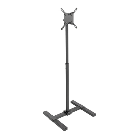
ricoo FS0522 quick start guide

AMSOIL
AMSOIL BMK-22 Installation and service instructions
Kargo Master
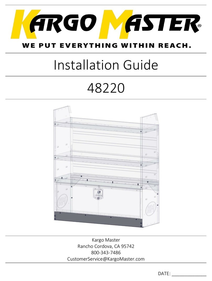
Kargo Master 48220 installation guide

Milestone AV Technologies
Milestone AV Technologies SIMPLICITY SLF2 installation instructions