Re-design up2you 9761586 User manual

1
Manual up2you-ARF
No.: 9761586 / 9756095
Content:
1. Introduction ........................................................................................................................ 2
2. Unpacking and First Assembly ............................................................................................ 3
3. Attachment of the Winglets ............................................................................................... 5
4. Integration of RC Components ........................................................................................... 7
5. Installation of Motorization Parts in the Electro-Section ................................................. 15
6. Adjustment of Center of Gravity (CG) and Elevons .......................................................... 19
7. Flying ................................................................................................................................. 26
8. For technical interested Modellers ................................................................................... 31
9. General Informations ......................................................................................................... 36

2
1. Introduction
The up2you-ARF is based on a series of predecessors which have been developed during the
last 20 years.
The main geometry data has been changed several times in order to optimize them for a
tailless wing in this size and weight.
The model has on optimized lift distribution and an airfoil which suits very well to the speed.
The profiled winglets increase the lift further.
Drag counts could be saved by deleting a “real” fuselage – this increases the gliding
performance of the model.
The mixture of balsawood, plywood, CFRP and GFRP enables a weight optimizes and
accurate construction.
Special attention has been put on an uncritical handling of the model. It can be flown very
slowly but the reaches its best performance with intermediate speed.
The model can be assembled very quickly with the arrestor hooks; therefore, it is well suited
for holydays or mountain hikes or just to fly a quick round after work.
Due to the possibility to install the electro-section between the wings, the pure sailplane is
enhanced to an electro-glider with the possibility to be launched in plain regions without any
further equipment (bungee).
The following assembly times should be considered:
Winglet Arrestment 2 hours
Integration of RC 5 hours
Integration of motor/controller 3 hours
GC and other adjustments 2 hours
3
2. Unpacking and First Assembly
Check if the following parts are included in the package:
Left and right wing
Left and right winglet
Electro-Section
Various small components to assemble
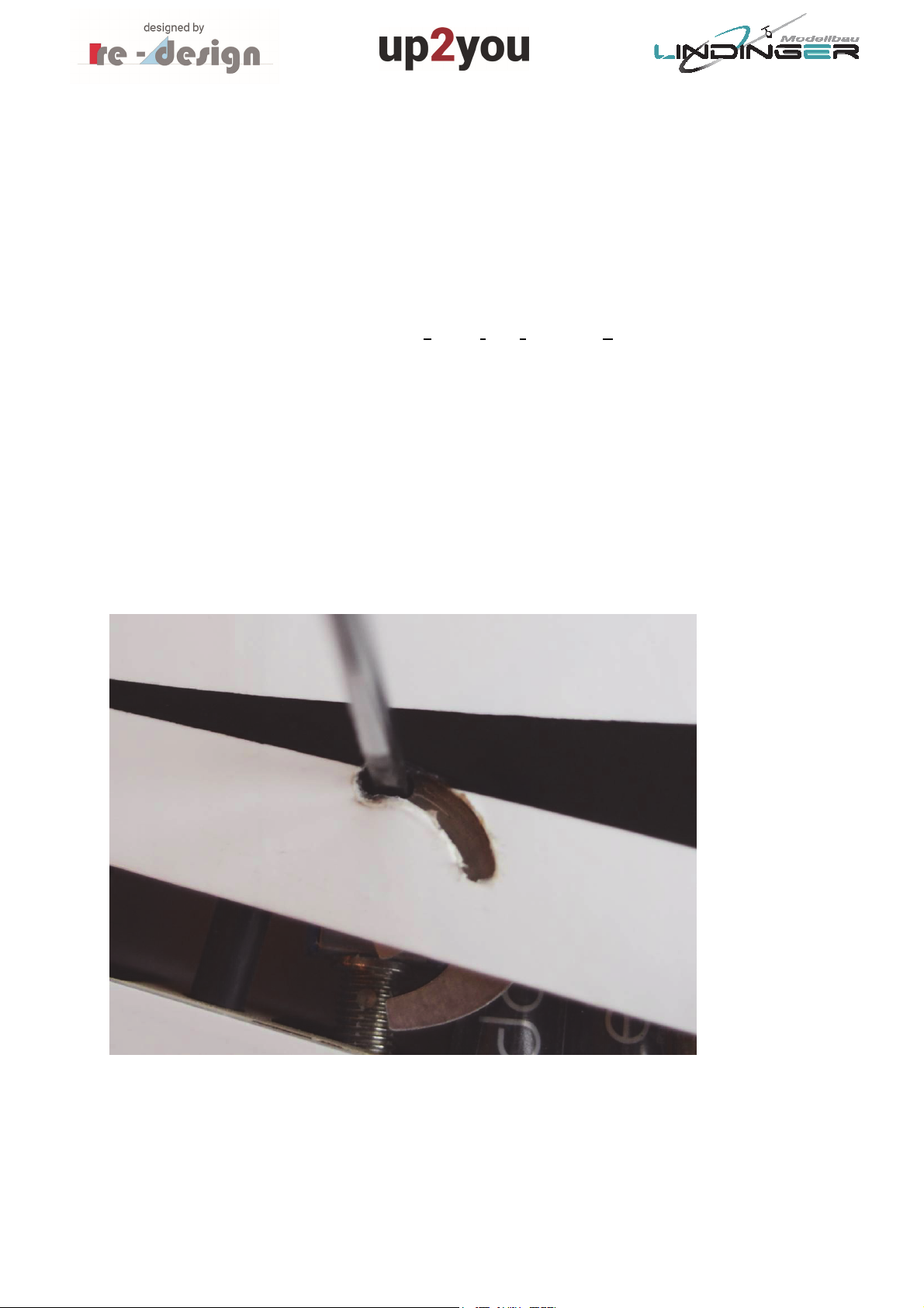
Assemble the wings with the short CFRP (carbon fibre reinforced plastic) connectors. The
arrestor hook must be fully opened – turn it fully to the left with a small screwdriver, refer to
figure 1.
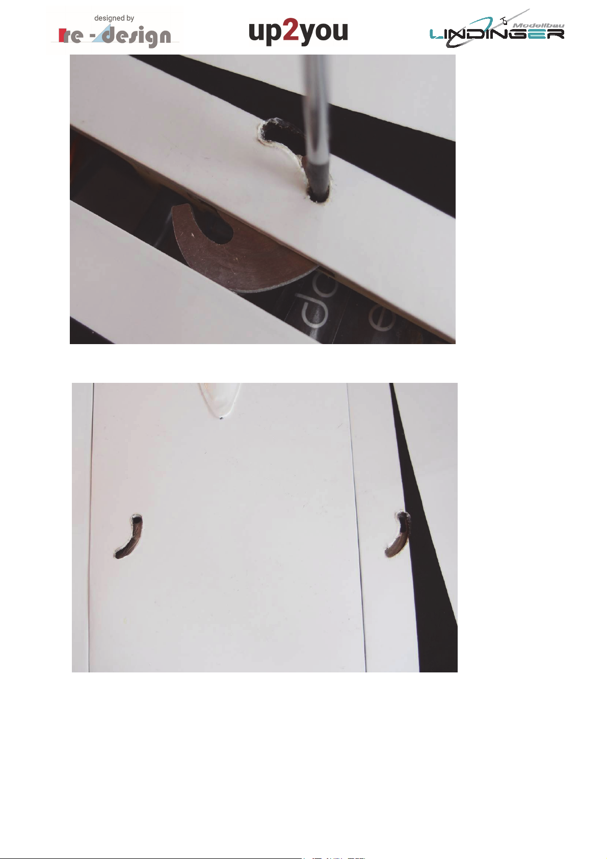
Then slide both wings together and arrest the hook, refer to figure 2. The arrestor hook will
be noticeable latch in the pin of the other wing.
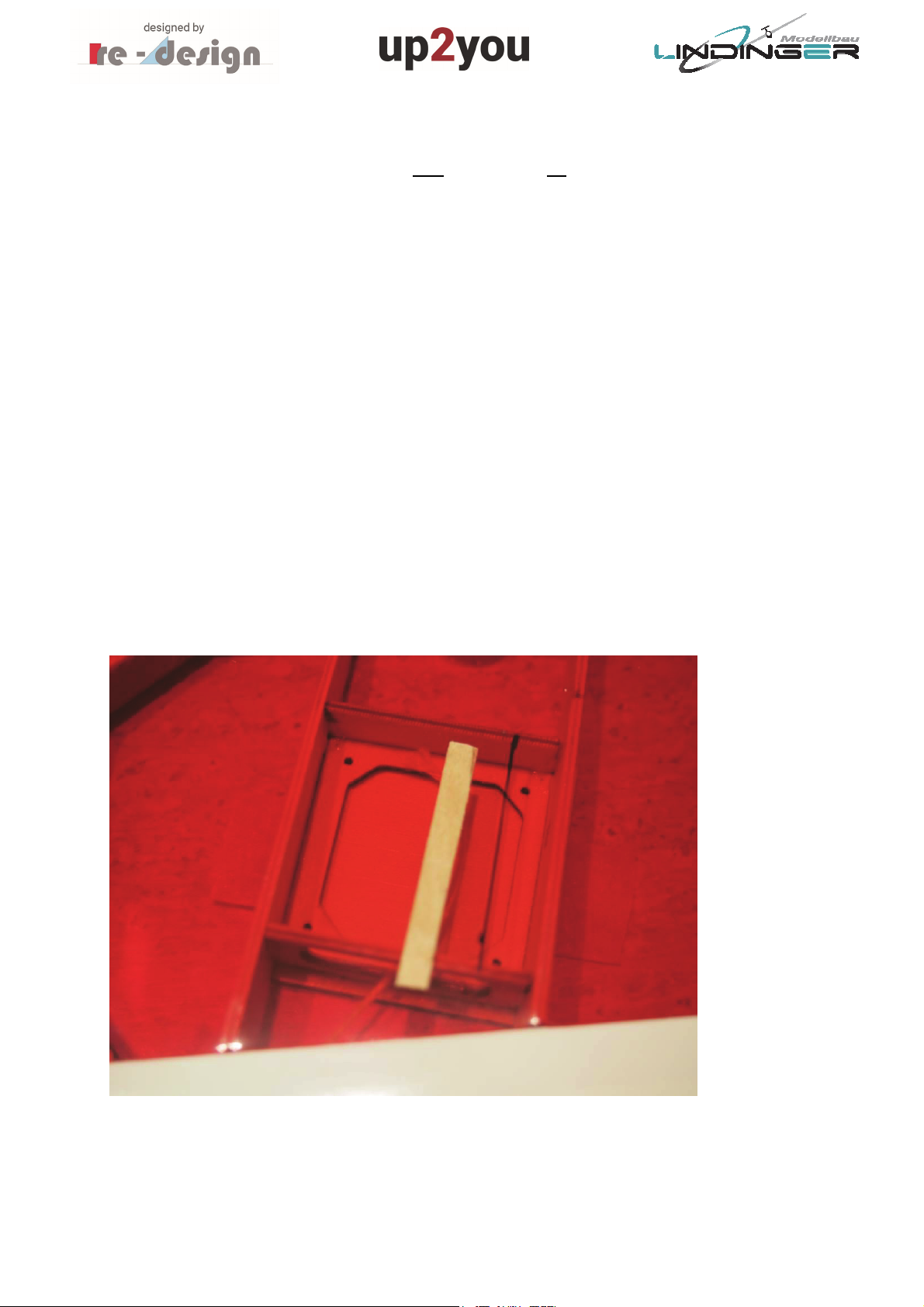
Assemble in the same way the Electro-section between the wings. Use for this the longer
CFRP connectors.
For the assembly of the Electro-glider, two arrestor hooks must be locked, refer to figure 3.
Figure 1, Fully opened Arrestor hook
4
Figure 2, Position of locked arrestor hook (wing not together for demonstration)
Figure 3, Tow arrestor hooks for the electro-glider

5
3. Attachment of the Winglets
In order to improve the transport of the glider for example on mountain hikes, the winglets
can be detached from the wings.
They are fixed by a small screw and two pins (2mm diameter, 10mm length). The two pins
must be glued into the baseplate of the winglets.
Before gluing them in the baseplate, they must be cleaned with acetone or thinner. Place
the winglet at its position at the wingtip and hold it. Then insert the pins from the outside of
the baseplate that approx. 5mm will be still visible, refer to figure 4. Ensure that the pins in
this position are already inserted in their bores in the outer rib of the wing.
Now fixate the winglet with the screw at the wing.
Apply epoxy on the part of the pins which are still visible and push them fully into the
baseplate so that they are aligned with the baseplate.
This method ensures that the winglets will be not glued on the outer rib of the wing which
would probably lead to problems to disassemble them.
After the epoxy has been hardened, the winglets can be removed.
Check the correct gluing of the pins by mounting the winglet again on the wing, refer to
figure 5.
Figure 4, Insertion of the winglet pins

6
Figure 5, Winglet correctly mounted on the wingtip
7
4. Integration of RC Components
The servos for the elevons (shortcut for Elevator and Aileron = combined function of
elevator and aileron) will be on the cover mounted which is fixated with four screws on the
lower surface to the wing. We propose to use the following servo:
ROBBE FS 166 BB MG Digital, #9756143
You may use other servos but the size shall not exceed the following dimensions:
25 x 25 x 9 mm (high x width x depth)
We propose to glue the servos after some adaption work on the cover with just 4 points of
glue. If a servo once fails, it can be easily removed by using a small grinding tool.
The connection from the servo the elevons control horn is on the upper surface of the wing
and therefore, the servo lever must be guided through the shrink film. Mark the cut-out for
the servo lever on the shrink film, refer to figure 6.
In order to achieve a protected edge of the film, you should glue a piece of 1mm plywood
under the cover before cutting out as it is shown in figure 6 and figure 7. Glue the shrink film
at the edge of the cut-out on the piece of plywood by using a modeler iron, refer to figure 7.
Figure 6, Marking of the cut-out for the servo lever

8
Figure
7,
Gluing of the shrink film on the piece of plywood (edge of cut-out)
After the cut-out is accomplished, insert the servo and cover into the wing in order to check
if it fits, refer to figure 8.
Attach the cover on the wing by using two screws. Check if the servo lever you are intend to
use is suitable regarding the length. There must be enough clearance for the clip of the
pushrod under full deflection of the servo.
Now, adjust the servo on its correct position (servo lever should be move more or less
parallel to the ribs) and fixate the servo with a point of glue, as it is shown in figure 9.
Then remove the cover and fixate the servo fully with 4 points of epoxy on the cover, refer
to figure 10.

9
Figure 8, Tentative insertion of the servo in the wing
Figure 9, Fixation of the servo

10
Figure 10, Servos glued on the cover with some points of epoxy
Now the servo cables will be soldered together and installed. You should use preferably very
thin cables in order to save weight. The loads on the servos are very low and therefore there
will be no high current through the cables.
Lengthen the cables should take into account some margin.
Instead of soldering, you may use connectors but we do not recommend this. A well
accomplished soldering connection is better than a connector. Connectors can be a source of
defects. Figure 11 shows the soldered and isolated cables.
Connect the cable to the cord which is inserted by the manufacturer in the wing. Use some
tape in order to have a connection which does not encumber the cable from slipping
through the wing. It is annoying if the connection opens during the installation of the cable –
possibly the wing must cut open if this happens. Figure 12 shows the connection.
Apply soft tension on the cord only. If you have to apply much tension, this could be an
indicator that somewhere the connection clamps in the wing. It is better in this case to pull
the cable a little bit back and then start again.
This manual suits for next models
1
Table of contents


