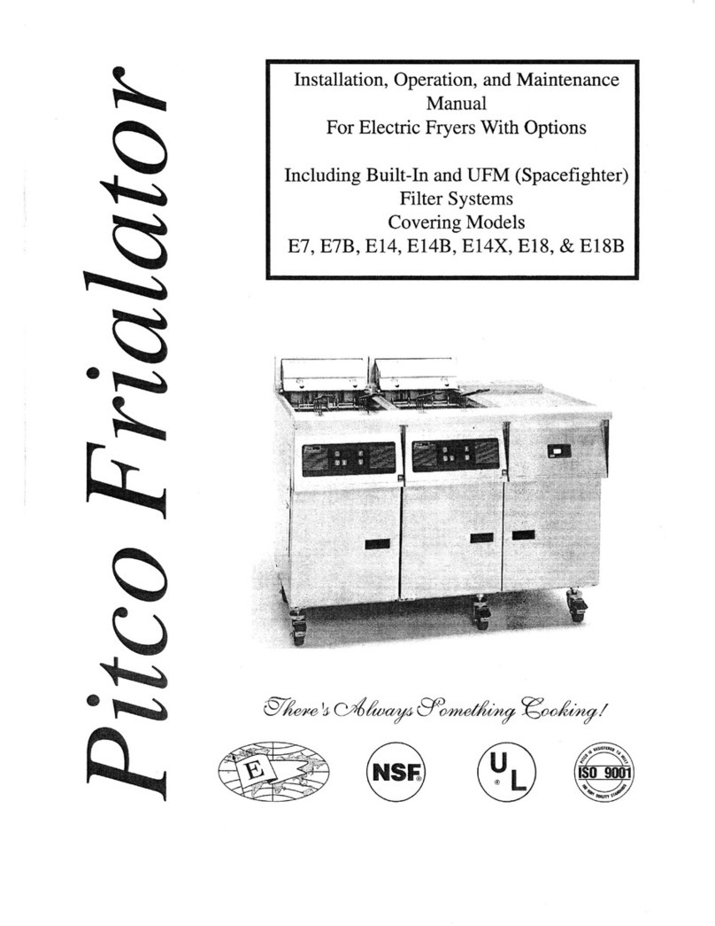
Pitco SELV14 User manual

IMPORTANT FOR FUTURE REFERENCE
PLEASE COMPLETE THIS INFORMATIONAND RETAIN
THIS MANUAL FOR THE LIFE OF THE EQUIPMENT.
MODEL #:____________________________________
SERIAL #:____________________________________
DATE PURCHASED:___________________________
ENGLISH
Installation & Operation Manual
REDUCED OIL VOLUME
FRYING SYSTEM
Covering Models
SELV14, SELV14T, SELV184
L20-406 Rev 7 (01/17)

L20-406 Rev 7 (01/17) Page 2
WARNING
DO NOT store or use gasoline or other ammable
vapors and liquids in the vicinity of this or any other
appliance.
WARNING
Improper installation, alteration, service or maintenance
can cause property damage, injury or death. Read the
installation, operating and maintenance instructions
thoroughly before installing or servicing this appliance.
WARNING
Installation, maintenance and repairs should be per-
formed by a Pitco Authorized Service and Parts (ASAP)
company technician or other qualied personnel. In-
stallation, maintenance or repairs by unauthorized and
unqualied personnel will void the warranty.
WARNING
Installation and all connections must be made accord-
ing to national and local regulations and codes in force.
WARNING
A country approved all pole circuit breaker with a
minimum open contact gap of 3mm must be used for
proper installation. (CE countries)
WARNING
During the warranty period if a customer elects to use
a non-original part or modies an original part pur-
chased from Pitco and/or its Authorized Service and
Parts (ASAP) companies, this warranty will be void. In
addition, Pitco and its afliates will not be liable for any
claims, damages or expenses incurred by the cus-
tomer which arises directly or indirectly, in whole or in
part, due to the installation of any modied part and/or
received from an unauthorized service center.
WARNING
This appliance, when installed, must be electrically
grounded in accordance with local codes, or in the ab-
sence of local codes, with the National Electrical Code,
ANSI/NFPA 70, or the Canadian Electrical Code, CSA
C22.2, as applicable.
WARNING
Adequate means must be provided to LIMIT the
movement or this appliance without depending on the
electrical cord connection. Single appliances equipped
with legs must be stabilized by installing anchor straps.
All appliances equipped with casters must be stabilized
by installing restraining chains.
WARNING
DO NOT alter or remove structural material on the ap-
pliance to accommodate placement under a ventilation
hood.
WARNING
This appliance is intended for commercial/professional
use only and should be operated by fully trained and
qualied personnel. It is not intended for continuous
mass production of food.
WARNING
This appliance is intended for indoor use only.
WARNING
If the power supply cord is damaged, it must be re-
placed by a Pitco Authorized Service and Parts (ASAP)
company technician, or a similarly qualied person in
order to avoid a hazard. In Europe, supply cords must
be oil resistant, sheathed exible cable not lighter than
ordinary polychloroprene or other equivalent synthetic
elastomer-sheathed cord (Code designation 60245 IEC
57).
WARNING
The power supply must be disconnected before servic-
ing, maintaining or cleaning this appliance.
WARNING
The appliance is NOT water jet stream approved. DO
NOT clean the appliance with a water jet or steam
cleaner.
WARNING
DO NOT attempt to move this appliance or transfer hot
liquids from one container to another when the unit is at
operating temperature or lled with hot liquids. Serious
personal injury could result if skin comes in to contact
with the hot surfaces or liquids.
WARNING
DO NOT sit or stand on this appliance. The appliance’s
front panel, tank, splash back, tank cover, work shelf,
drain board is not a step. Serious injury could result
from slipping, falling or contact with hot liquids.
WARNING
NEVER use the appliance as a step for cleaning or
accessing the ventilation hood. Serious injury could
result from slips, trips or from contacting hot liquids.
WARNING
Potential re danger exists if the cooking oil level is
below the minimum indicated level. The cooking oil
level should NOT be allowed to fall below the minimum
indicated level line at any time. The use of old cooking
oil can be dangerous as it will have a reduced ash
point and be more prone to foaming over.
WARNING
The contents of the crumb catch and/or lter pan of any
lter system must be emptied into a reproof container
at the end of each day. Some food particles can spon-
taneously combust if left soaking in certain types of oil
or shortening.
WARNING
Completely shut the appliance down when shortening/
oil is being drained from the appliance. This will prevent
the appliance from heating up during the draining and
lling process. Serious injury can occur.
WARNING
DO NOT operate appliance unless all panels and ac-
cess covers are attached correctly.
WARNING
It is recommended that this appliance be inspected by
a qualied service technician for proper performance
and operation on a yearly basis.
TO THE PURCHASER, OWNER AND STORE MANAGER
Please review these warning prior to posting them in a prominent location for reference

L20-406 Rev 7 (01/17) Page 3
TABLE OF CONTENTS
1 THEORY OF OPERATION 5
2 INSTALLATION 6
2.1 CHECKING AND UNPACKING YOUR NEW APPLIANCE 6
2.2 GENERAL INSTALLATION REQUIREMENTS 7
2.3 INSTALLATION CLEARANCES 7
2.4 LEVELING THE FRYER- LEGS/CASTERS 8
2.5 ELECTRICAL CONNECTIONS 9
2.6 FIXED WIRING and RESTRAINT CABLE 10
2.7 VENTILATION AND FIRE SAFETY SYSTEMS 11
2.8 INSPECTION 11
2.9 INITIAL CLEANING 12
3 OPERATION 13
3.1 OPERATIONAL FEATURES 13
3.2 FILLING THE FRY POT 15
3.3 APPLIANCE START UP 16
3.4 APPLIANCE SHUTDOWN 16
4 OIL MANAGEMENT 17
4.1 COOKING 17
4.3 BASKET LIFT OPERATION 17
4.4 FRESH OIL TOP OFF FUNCTION 17
4.5 AUTOMATIC OIL TOP OFF SYSTEM (OPTION) 17
4.6 QUICK STRAIN FILTERING 18
4.6.1. NON-AUTO Filter models 18
4.6.2 AUTO FILTER MODELS 18
5 PREVENTATIVE MAINTENANCE 19
5.1 DAILY PREVENTATIVE MAINTENANCE 19
5.1.1 DAILY FILTERING 19
5.1.2 FLUSH HOSE OPERATION (if equipped) 20
5.1.3 REPLACING THE FILTER MEDIA (if equipped) 20
5.1.4 CLEANING THE CABINET 21
5.1.5 FILTER CLEANING (If Equipped) 21
5.1.6 APPLIANCE INSPECTION 21
5.2. WEEKLY PREVENTATIVE MAINTENANCE 21

L20-406 Rev 7 (01/17) Page 4
5 PREVENTATIVE MAINTENANCE (continued)
5.3 MONTHLY PREVENTATIVE MAINTENANCE 22
5.3.1 BOIL OUT PROCEDURE 22
5.3.2 TEMPERATURE CHECK 22
5.4 ANNUAL/PERIODIC PREVENTATIVE MAINTENANCE AND INSPECTION 23
5.4.1 SAFETY EVALUATION 23
5.4.2 MECHANICAL INSPECTION 23
5.4.3 TEMPERATURE CONTROL SYSTEM 23
5.4.4 FILTER SYSTEM (IF EQUIPPED) 23
5.4.5 HEATING ELEMENT 23
5.4.6 CONTROL BOX & ELECTRICAL COMPONENTS 23
6 TROUBLESHOOTING 24
6.1 POWER FAILURE 24
6.2 HIGH TEMPERATURE LIMIT 24
6.3 DRAIN VALVE INTERLOCK 24
6.4 FRYER TROUBLESHOOTING CHART 25
6.5 FILTER TROUBLESHOOTING CHART 26
6.6 CONTROLLER DISPLAYS 27

L20-406 Rev 7 (01/17) Page 5
The Pitco Reduced Oil Volume fryer works very similarly to the Pitco standard electric fryer.
Other than rotating elements (for cleaning), the appliance functions nearly the same.
The Low Oil Volume Fryer has a reduced cold zone to signicantly reduce oil usage and extend
oil life. This smaller zone may require more frequent ltering depending on the product being
fried.
Upon turning the fryer on, the high limit closes the (side on) safety contactor which stays closed
until the fryer is turned off. If the oil temperature exceeds 450 °F, the high limit opens and pre-
vents further operation until the cooking oil has reached a safe cooking temperature. This plac-
es a minimum duty cycle on the safety (side on) contactor to insure its proper operation when
needed. The “heat demand” contactor opens and closes on demand from the primary control to
maintain the desired cooking temperature. When the “heat demand” contactor closes, it ener-
gizes the heating elements in the fry pot. Near the fryer heating elements, the temperature and
high limit sensor probes can be found. The temperature probe provides a signal to the primary
control, sensing the oil temperature in the fry pot.
The fryer is equipped with a manual “ADD OIL” function that can transfer fresh oil from a JIB
(Jug in Box) located under the fryer or a bulk oil management system. The operator can use
the manual “ADD OIL” button as needed to replenish any oil consumed in the cooking process.
It is recommended that oil only be added when the fry pot is at the desired temperature, and
that the “ADD OIL” function not be used to ll an empty fry pot from the JIB.
Optional Automatic Top Off: If equipped, the fryer (only when operating at desired temperature)
senses the oil level and replenishes consumed oil only between cook cycles. There are no
programming options for the operator or service technician, the control functions like any other
Pitco electric fryer computer control. The “ADD OIL” function (described above) is present with
models equipped with Auto Top Off.
1 THEORY OF OPERATION

L20-406 Rev 7 (01/17) Page 6
2.1 CHECKING AND UNPACKING YOUR NEW APPLIANCE
Your new Pitco appliance has been carefully packed into one crate. Every effort has been
made to ensure that it is delivered to you in perfect condition. Pitco does not assume responsi-
bility for damage or loss incurred in transit.
1. Upon Delivery, inspect for visible shipping damage in the presence of the trucking
operator. If something appears damaged, le a claim for damages regardless of
extent.
2. Unpack and inspect unit for damage. Contact the shipper within 15 days and le
a concealed damage claim; the shipper is only responsible for concealed dam
age for 15 days after delivery.
3. Remove the unit from the shipping pallet:
Remove the lter pan, and JIB pan from unit before attempting to
dismount the unit from the shipping base.
4. Do not allow the full weight of the unit to rest on the legs or caster when
removing the appliance from the shipping pallet. The casters can be bent or
damaged if too much weight or force is applied to them from improper handling.
5. Check the packing list enclosed with your appliance to ensure that you have
received all the parts to the appliance. Refer to gure 1 for accessory
identication. If you are missing any parts, contact the dealer from whom the
appliance was purchased.
6. Using the front cover of this manual, record the following for warranty service or
future reference: 1. Your Pitco model number. 2. Fryer serial numbers (Found on
the inner door of each fryer). 3. The date purchased from your dealer invoice.
Once you have completed the above, the appliance is ready to be installed.
FRYER ACCESSORIES
Item # Part # Description Qty
1A3301001 Drain Clean Out Rod 1
2PP10056 Frypot Cleaning Brush 1
3 P6072145 14” Size Fry Baskets 2
4B6681201 Filter Sediment Scoop 1
5 A6667104 Filter Media Starter Pack 1
6A1108002 Removable Basket Hanger 1*
* Quantity one per fry pot.
2 INSTALLATION

L20-406 Rev 7 (01/17) Page 7
2.2 GENERAL INSTALLATION REQUIREMENTS
The installation of this appliance must be performed by an authorized service professional. A
qualied professional will ensure that the installation is safe and meets local or national build-
ing, electrical, and re codes.
Where conict exists between instructions in this manual, and local, or national codes or reg-
ulations, installation and operation shall comply with the codes or regulations of the locale in
which the appliance is installed.
2.3 INSTALLATION CLEARANCES
The clearances shown below are for combustible and non-combustible installations and will
allow for safe and proper operation of your appliance
Back 6.0 (15.24) 0.0 (0.0)
Sides 6.0 (15.24) 0.0 (0.0)
Aisle 35.0 (88.9) 35.0 (88.9)
Combustible Construction Non-Combustible Construction
Inches (Centimeters) Inches (Centimeters)
WARNING
DO NOT obstruct the ow of ventilation air openings around the appliance. Adequate
clearance around the appliance is necessary for servicing and proper component ven-
tilation. Ensure that you meet the minimum clearance requirements specied in this
manual.
WARNING
DO NOT install this appliance next to a water cooker, or use in any way in which water
can come in contact with the hot oil. Splash over of water into hot oil may result in a
steam eruption, potentially causing hot oil to be ejected from the fryer, and creating a
burn hazard.
INSTALLATION
CAUTION
It is important that you read and understand this manual before
installing, operating or servicing this appliance. Be sure to
retain this manual for future reference.

L20-406 Rev 7 (01/17) Page 8
CAUTION
To prevent equipment damage and/or personal injury, do not tilt the appliance onto any two of
its casters or legs, or pull the appliance by the splash back.
WARNING
This appliance must be installed with the legs or casters provided by the manufacturer.
WARNING
DO NOT perform leveling procedure when appliance is in operation or full of hot liquids.
Serious injury could result.
2.4 LEVELING THE FRYER- LEGS/CASTERS
When you receive your appliance, it is completely assembled with legs or optional casters. This ap-
pliance must be installed with legs or casters; it cannot be curb mounted, or sealed to a base. Curb
mounting will seriously inhibit this appliance’s ability to effect proper component ventilation. The sup-
plied legs or casters provide the necessary height to meet sanitation requirements and assure adequate
air supply for electrical component ventilation. To level the fryer, use the following procedure.
Required tools: A large pair of water pump pliers, a medium sized at blade screwdriver and a 12”
(30.5 cm) long level.
1 Position appliance in nal installed location.
2 Apply level across front, and then the left and right side of unit, determine lowest point
and distance to level.
3 Add the distance determined in step 2 to caster or leg on the lowest corner of appliance.
a. Swivel casters- loosen 2 set screws (A)
b. Legs and swivel casters-. Adjust the height of the leg / caster by turning
adjustment collar/ foot (B) with water pump pliers until desired change in height is
achieved.
c. Swivel casters only: Retighten set screws (A).
d. Fixed casters- Adjust height by moving wheel and axle to alternate holes (D) in
wheel bracket as needed. Refer to “FIXED” type caster as shown below.
4 Adjust remaining casters or legs as needed to insure the appliance is supported evenly
at each caster/leg contact point.
2 INSTALLATION

L20-406 Rev 7 (01/17) Page 9
2.5 ELECTRICAL CONNECTIONS
It is advised that this appliance be connected to a power supply that is controlled by the ventilation system. This
will prevent the appliance from being operated without the ventilation hood on. If your appliance is single phase,
it requires a hardwired, exible conduit electrical connection, using conductors sized appropriately for the power
requirements listed below. Hardwired units require installation of a restraint device mounted to a safe and substan-
tial element of the building’s structure.
Electrical
Requirements Nominal Amps Per Line (50/60 Hz)
Single Phase (2 Wire and Ground) 3 Phase (3 Wire and Ground) 3 Phase Wye (4 Wire and Ground
Model kW 200V 208V 220V 230V 240V 480V 200V 208V 220V 230V 240V 480V 346/200V 380/220V 400/230V 415/240V
SELV14
SELV14T
*
14 65 67 65 61 58 29 37 39 37 35 34 17 21 21 20 20
SELV14
SELV14T
*
SELV184
17 79 82 78 74 71 36 46 48 45 43 41 21 27 26 25 20
* Measurements include both tanks. 1. Each fryer requires its own separate power cord. 2. 200V units will operate at 92% of rated power. 3. Power
supply for Basket Lifts and Filter Motor is wired to the fryer’s high voltage line terminal block, except for 480V, which requires a separate single phase
power service for the Filter Motor and Basket Lifts (if equipped) rated at 115V, 8.0 A for North America or 220-240V, 4A for Export to be installed.
CAUTION
Connecting the appliance to the wrong power supply may damage the appliance and void the warranty.
WARNING
This appliance must be connected to a power supply having the same voltage and phase as specied on the
data plate located on the inside of the appliance door. DO NOT connect the appliance to an electrical supply
other than that indicated on the data plate. Electrical connection should be performed by a qualied
electrician.
WARNING
The electrical connection used by this appliance must comply with local codes. If there are no local codes that
apply, refer to the National Electrical Code (NEC), ANSI/NFPA 70 for installation in the US. In Canada, refer to
CSA Standard C22.2 and local codes. In all other cases, refer to local and national codes and regulations.
The appliance must be grounded in accordance with local code, comply with the NEC and ANSI/NFPA No. 70
latest edition (for US and Canada). In all other cases, refer to local and national codes and regulations. To
comply with EU requirements, European models are equipped with an equalization-bonding clamp.
An equalization bonding lead must be connected to this clamp to provide sufcient protection
against potential difference. This clamp, located on the rear of the appliance, is marked with the
following symbol.
WARNING
A country approved all pole circuit breaker with a minimum open contact gap of 3mm must be used for proper
installation. (CE countries)
CAUTION
Leakage current of this appliance may exceed 10 mA. When permanently connected, a high integrity protective
system employing an RCD rated at 30 mA must be used with this appliance.
WARNING
This equipment must be installed so that the plug (if used) is accessible unless other means for disconnection
from the power supply (e.g.: circuit breaker) is provided.
INSTALLATION

L20-406 Rev 7 (01/17) Page 10
2.6 FIXED WIRING and RESTRAINT CABLE
If your appliance was not equipped with an optional cord set and plug, xed connection to the electrical power
supply will be required. This must be performed by a licensed electrician. A licensed electrician will properly size
the wiring and ensure that the installation meets all local or national codes and warnings in force when making
eld connections to mains.
Fixed wiring connection procedure:
1. Remove the fryer entrance box cover, Figure 2.6.1.
2. Insert power cable/conduit through hole in fryer cabinet, Figure 2.6.2. Use care when
routing power cable/conduit through the fryer to not interfere with actuator movement.
3. Referring to gure 2.6.3, Install cable strain relief in housing cutout (1). Attach power
cable wires to terminal block (2) per connection diagram on fryer door.
4. Attach a movement restraint cable assembly to any fryer that is not connected with a
cord and plug, Figure 2.6.4.
WARNING
If this appliance is permanently connected to xed wiring, it must be connected by means of copper wires hav-
ing a temperature rating of not less than 167°F (75°C), and have a local means of disconnection from all poles
from the mains included in the xed wiring in accordance with local codes.
WARNING
All power connection wiring for this appliance must be made in accordance with the wiring diagrams(s) located
on the appliance.
Figure 2.6.1 - (Drain line removed for clarity). Figure 2.6.2 - Insert exible conduit through cabinet as shown to
prevent contact with moving parts.
Figure 2.6.3 - Wire housing strain relief hole: 2” or 1.75”
diameter. Figure 2.6.4 - Fryers on casters, and/or installed with exible
conduit must have a restraint cable installed between the fryer
and substantial structural element to prevent strain on conduit.
INSTALLATION
Other manuals for SELV14
1
This manual suits for next models
2
Table of contents
Other Pitco Fryer manuals




Pitco
Pitco SGH50 Operating and installation instructions

Pitco
Pitco TURBOFRY 2000 User manual

Pitco
Pitco SE Series User manual

Pitco
Pitco MGII Service manual

Pitco
Pitco 24RUFM User manual

Pitco
Pitco L22-355 User manual

Pitco
Pitco SG6H User manual

Pitco
Pitco Frialator SF14 UFM Guide

Pitco
Pitco SG14C User manual

Pitco
Pitco VF35 User manual