
Perry Electric V002 Series Guide

• Wireless connection
• Equipped with a back-lit LCD display with
“White-LED” technology
• Easy to program via APP
• Weekly programming
• “All glass” finish for a pleasant and modern design
Wi-Fi THERMOSTAT
Installation and use manual
ENGLISH
PE - DECRPE024EN 01/20
Wall mounting
Programs
for day
C
AP

INDEX
WARNINGS .............................................................................................................................................pag. 3
KEYS FUNCTION LEGEND ...................................................................................................................pag. 4
DISPLAY LEGEND pag. 5
INSTALLATION ....................................................................................................................................... pag. 6
ELECTRICAL CONNECTIONS ............................................................................................................. pag. 8
..................................................................................................................................
FASTEN OR REMOVING THE THERMOSTAT FROM THE WALL BASE
THERMOSTAT ASSOCIATION TO ROUTER
pag. 10
pag. 12
pag. 14
THERMOSTAT OPERATION MODE
THERMOSTAT TECHNICAL SPECIFICATIONS
SIMPLIFIED EU DECLARATION OF CONFORMITY
pag. 16
OPERATIONS CARRIED OUT DIRECTLY BY THERMOSTAT pag. 15
2
The full text of the EU Declaration of Conformity is
available at the Internet address shown on the label:
The manufacturer declares that the type of radio
equipment listed below complies with Directive
2014/53/EU (RED). Via MILANESE, 11 - 22070 VENIANO (Como)
ITALY - www.perry.it
Tel. 39-031-8944.1 Fax 39-031-+ + 8365201
1TXCR029WIFI V002
PERRY ELECTRIC S.r.l.
Manufacturer, Fabricat , Fabbricante, Fabricante:, Fabrikant
Type , Tipo:, Typen
http://www.perry.it/it/dichiarazioni.aspx
Series, serie:
............................................................................pag. 2
SYSTEM ASSEMBLY........... ...................................................................................................................
EU SIMPLIFIED CONFORMITY DECLARATION
pag. 11
......... .............................................................................
.....................................................................................................
...........................................................
...................................................................................
...........................................

Packaging components (any plastic bags, PVC suspensions,
etc.) must be kept out of reach of children.
Ensure the product is intact once it is removed from its
packaging.
Carefully read the instruction manual before using the
product as it provides important guidelines regarding
safety, installation and use. The instruction manual
must be preserved with care for future reference.
The thermostat is not intended for use by
persons (including children) with reduced physical, sensory
or mental capabilities, or by those with a lack of experience
and knowledge of the instructions, unless they are supervised
or have received the necessary instructions concerning use of
the device by a person responsible for their safety. Children
should be supervised to ensure that they do not play with the
device.
programmable
The installation and electrical connection of the
programmable thermostat must be implemented
by qualified electrician and in conformity with current
laws and regulations.
only
a
If necessary, clean the thermostat with a
slightly damp cloth.
programmable
Important: for the system modes and operation
of the W F temperature control system and for
correct installation, also see the specific
manual of the APP.
i- i
Radio frequency waves emitted by the
wireless thermostat are not
a risk to human or animal health.
programmable
Important: the manufacturer reserves the
right to introduce any technical and/or
constructive changes deemed necessary,
with no prior notice.
3
Important: the manufacturer shall not, under
any circumstances, be liable if the products
fail to operate due to the interruption of the
internet network or unavailability of these
resources: Cloud, Server, Portal.
Important: internet access costs are charged
to users according to the rates of their mobile
phone provider.
INTERNET
offline
WARNINGS
By ensuring this product is disposed of correctly, you will help prevent potential negative consequence for the environment and human health,
which could otherwise be caused by inappropriate waste handing of this product.
The recycling of materials will help to conserve natural resources. For more detailed information about recycling of this product, please contact
your local city office, your house hold waste disposal service or the shop where you purchased the product.
- sales points, in case you buy a new and similar product;
- local collection points (waste collection centre, local recycling center, etc...).
This symbol on the product or its packaging to indicates that this product shall not be treated as household waste.
Instead, it shall be handed over to the applicable collection point for the recycling of electrical and electronic equipment, such as for example:
DISPOSAL OF ELECTRICAL & ELECTRONIC EQUIPMENT

KEYS FUNCTION LEGEND
Thermostat OFF Increase
temperature
Decrease
temperature (creates a temporary Wi-Fi network)
Access point
C
F
AP
Touching any key activates back-lighting, displaying the
words selection and navigation press the desired key
within 6 sec. to vary the settings (touching any key
reactivates a 6 sec time-out).
;
Note: with fixed backlighting (which can be set from
the APP); besides being always lit, the keys can be
first touch operated
DISPLAY AND KEY BACK-LIGHTING
4
Important!
THE COLOUR OF THE KEYS varies depending , as per the rule below:on the temperature Set and operating at that moment
Setting lower than 18,1°C =
Setting from 18,1 to 21°C =
keys lit in green
keys lit in blue
keys lit in redSetting over than 21°C =
Setting over than 26°C =
Setting from 26 to 23°C =
keys lit in green
keys lit in blue
keys lit in redSetting lower than 23°C =
in SUMMER mode:
in WINTER mode:

Current time
Key lock
Away mode
Thermostat
connected to Wi-Fi network
Cooling mode
Detected room temperature
Set temperature
Heating mode
Connected utility on
(ex. Boiler in operation: + flashing)ON
DISPLAY LEGEND
Manual operation
temporary or permanent
Days of
the week
5
C
F
In communication
with the Perry Server
Thermostat
not connected to Wi-Fi network
(exclusively settable
from APP)
Operation from
program entered
with the APP

During installation, some precautions must be taken in order not to limit or inhibit the range of the radio waves between
and thermostat:
Wi-Fi Router
- install the appliance away from metal furniture or structures which could alter or screen propagation of radio signals;
- make sure that there are no electrical or electronic devices (television, microwave oven, etc.) within a range of at least 1 m from the
appliance.
Note: if there are no obstacles between the thermostat and , the “open air” range is approximately 00 m; indoors
with the presence of walls, the range is approximately 0m (see “technical data”).
the Wi-Fi Router 1
2
6
Radio range warnings
INSTALLATION
Below are some examples of mitigation related to
materials, which impact on the "Free air" range
declared above.
Radio range decreases significantly when the
components are interposed between the obstacles.
This attenuation varies in different degrees
depending on the type of material the walls or
barriers to cross are made of.
The presence of noise or electromagnetic
interference sources can also reduce the indicated
radio range.
DENSE VEGETATION
trees, hedges, shrubs, etc.
radio range reduction of 10%÷25%
WOOD OR
PLASTERBOARD WALLS
radio range reduction of 10%÷30%
BRICK OR STONE WALLS
radio range reduction of 40%÷60%
CONCRETE WALLS
radio range reduction of 50%÷70%
METAL WALLS and/or FLOORS
radio range reduction of 65%÷90%

88,5
128,5
INSTALLATION EXAMPLE
Install the thermostat preferably at a height of 1.50 to 1.60 m from
the floor, far from sources of heat, air inlets, doors or windows and
anything that may alter its operation.
FASTENING THE WALL BASE
Per assicurare un corretto montaggio del
cronotermostato alla base a parete, la stessa non deve
presentare incurvature dovute all’eccessivo serraggio
delle viti di fissaggio nella scatola rettangolare o tonda
DIMENSIONS
h 1,5 m
26
Wall mounted - onto a recessed rounded box with a
rectangular 3 module box.
or
Thermostat installation: independent fixed
7
!Switch off mains power 230V~
!Fasten the base of th thermostat with the screws supplied: to the
wall, to the rounded or rectangular recessed box via the relative
paired holes .
e
A
E
A
A
C
D
B
To ensure the hermostat is fitted correctly to the wall-
mounted base, the latter must not be bent due to the
screws being tightened too much to the rounded or
rectangular recessed box.
t
C- thermostat hooking teeth
recessed box.
E- screws to fasten the wall base to the rectangular or round
D- thermostat fastening slot
B- wire passage from corrugated tubes, round or rectangular
recessed box
wall-mounted, round or rectangular recessed box
A- base fastening holes:
INSTALLATION

Important: t only ahe installation and electrical connection of the thermostat must be implemented by qualified electrician and in
conformity with current laws and regulations. The manufacturer declines all liability in connection with the use of products subject
to special environmental and/or installation standards.
ELECTRICAL CONNECTIONS
Switch off mains power 230V~
-3(NO)normally open contact
-2t (NC)normally closed contac
1- common (C)
!connect the device to be controlled to the terminals:
Relay terminals
230V~
N
230V~
230V~ power supply terminals
!n° 4 - LINE
!n° 5 - NEUTRAL
!Connect line voltage power supply to the terminals:
NO
NC
C
L
8
Attention!
connect the device to be
controlled

Connection to a boiler
NO
NC
C
123
BOILER
Connection to a motorized valve
NO
NC
C
123
LOAD
M
opens
closes
230V~
NL
230V~
After having completed the electrical connections, secure the body of the thermostat to the wall base as instructed in the following paragraph.
with heavy inductive loads (pumps and solenoid valves), connecting an RC filter parallel to the load is recommendable.
230V~N
L
Examples of electrical connections to devices to be controlled
ELECTRICAL CONNECTIONS
9

FASTEN OR REMOVE THE THERMOSTAT TO/FROM THE WALL-MOUNTED BASE
!Apply the terminal cover to the base, securing it to hook .E
!To remove the cover, use a small screwdriver on hook for leverage.E
After having made the electrical connections:
Hook the thermostat to the wall base in teeth . Then press the
thermostat at the bottom to complete fastening in slot .
(CLICK indicating the correct fixing
C
D
).
1°
3°
2°
E
C
D
C
Disconnect the 230V~ mains voltage
ATTENTION!
Removing the thermostat
from the wall base
D
Unhook the thermostat from the wall base, using a
screwdriver in the specific slot in the lower part of the
device for leverage, then turn to remove it.
D
10
This manual suits for next models
1
Table of contents
Other Perry Electric Thermostat manuals

Perry Electric
Perry Electric TE541 User manual

Perry Electric
Perry Electric RECESS Series User manual

Perry Electric
Perry Electric MODULE Series User manual

Perry Electric
Perry Electric TE540 User manual

Perry Electric
Perry Electric Recess Series User manual

Perry Electric
Perry Electric 1TX CR028WIFI Guide
Perry Electric
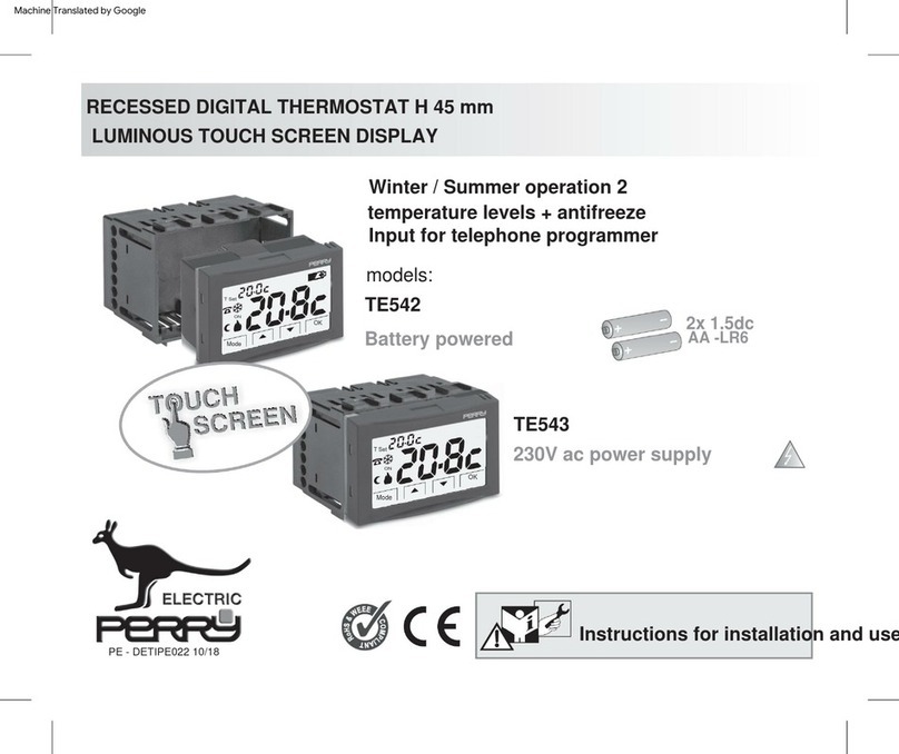
Perry Electric TE542 User manual
Popular Thermostat manuals by other brands


Saswell
Saswell SAS920XWHB-7-S-RF User manual and warranty card

Aircalo
Aircalo TFP1-ET85P2 operating manual

Honeywell
Honeywell CM721 user manual

Carrier
Carrier DEBONAIR 33CS Installation and operating instructions

Lennox
Lennox iHarmony Zone Thermostat Installation and setup guide

Gemtech
Gemtech GT7000 Operation


