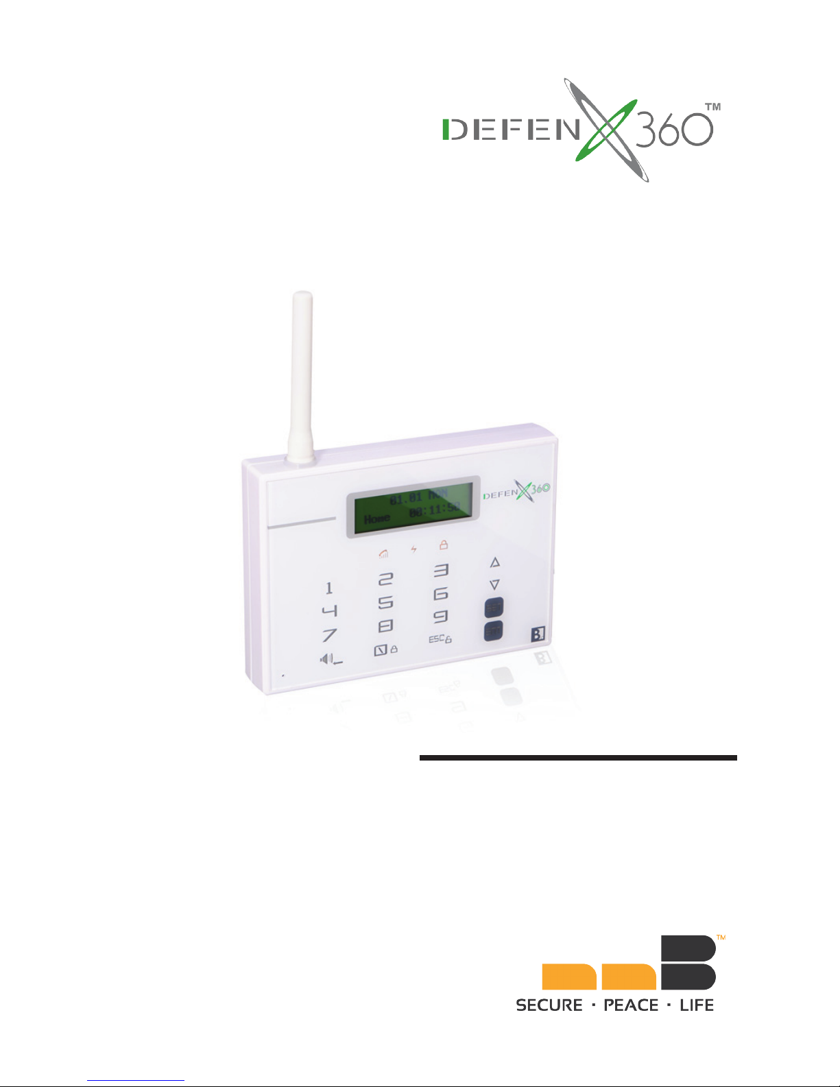
nnB Technology DefenX360 Series Installation instructions

Wireless GsM lCD TouChpaD
seCuriTy alarM sysTeM
Model: DX360 Series
Installation & Operating Manual
nnB Technology Limited

Thank you for choosing
Please read this guide thoroughly and carefully before applying the system in use.
Keep this manual safe for future reference.
Copyright Notice
This manual is furnished under license and may be used or copied only in accordance with the terms of such
license. Except as permitted by such license, no part of this publication may be reproduced, stored in a retrieval
system, or transmitted, in any form or any means, electronic, mechanical. Recording, or otherwise, including
translation to another language or format, without the prior written permision of nnB. The content of this manual
is furnished for informational use only, is subject to change without notice, and should not be construed as a
commitment by nnB. nnB assumes no responsibility or liability for any errors or inaccuracies that may appear in this
book. All other product names, trademarks and registered trademarks in this document are the properties of their
respective holders.
Warranty
nnB warrants this product will be free from defects in materials and workmanship for period of time specied on the
product packaging. This limited warranty shall commence from the date of purchase. nnB products warranty is not
transferable and is limited to the original purchaser. If the product is found to be defective then, as your sole remedy
and as the manufacturer’s only obligation, nnB will repair or replace the product. The warranty shall not apply to
products that have been subjected to abuse, misuse, abnormal electrical or environmental conditions, normal wear
and tear or any condition other than what can be considered normal use.
Limitation of Liability
The liability of nnB arising from this warranty and sale shall be limited to a refund of the item price. In no event shall
nnB be liable for costs of procurement of substitute products or services, or for any lost prots, or for any incidental,
consequential, direct or indirect damages, however caused and on any theory of liability, arising from this warranty
and sale. These limitations shall apply not withstanding any failure of essential purpose of any limited remedy.

Foreword
The DefenX360TM Wireless Alarm System is designed to provide a high standard of security protection for your home
and ofce. The system is congured for ease of installation and operation. However, it is strongly recommended to
read and fully understand the advice and installation procedures contained in this manual before proceeding with the
installation and operation of your DefenX360TM.
General System Information On DefenX360TM
This device is a part of the nnB home control system and works with the bi-directional wireless protocol.
All devices are delivered in a standard conguration. All current technical documents and updates are provided at
www.nnbtech.com.
Should you encounter any difculty in the set-up or operation of your security system, rstly refer to the “Common
Problems and Solutions” guide at the rear of this manual. In the unlikely event of a problem occurring with your
DefenX360TM, switch off at the mains sockets, pull out the plugs, and contact your dealer immediately.
General Information On Radio Operation
The radio transmission is on a non-exclusive transmission path with possibility of interference occurring. Other
interfering sources can be caused by switching operations, electrical motors or defective electrical devices.
The range of transmission within buildings can greatly deviate from open air distances. Besides the transmitting
power and the reception characteristics of the receiver, environmental inuences such as humidity in the vicinity and
local structures also play an important role.
Compatibility Of This Manual
This manual should be used with DefenX360TM Series only.
CE & FCC Compliances Statement
CAUTION: Changes or modications without approved by nnB could void your authority to use this equipment.
This equipment has been tested with the listed standards below and found in compliance with the LVD Directive
2006/95/EC and the EMC Directive 2004/108/EC. It is possible to use CE marking to demonstrate the compliances.
EN 301 489-1 V1.8.1
EN 301 489-7 V1.3.1
EN60950-1: 2006 + A11: 2009 +A1: 2010
EN50131
This product complies with FCC PART 15B / 22H / 24E, and the operation is subject to the
following conditions:
1. This device may not cause harmful interference and
2. This device must accept any interference received.

Safety Instructions 5
Symbols 5
Your Quick Guide To DefenX360TM System
Installations 6
Your Quick Guide To DefenX360TM System
Operations 8
Key Buttons 8
Main Alarm Host And Wireless Remote Keypad: 8
Emergency Contact List 8
DefenX360TM Luminous Signal Indicators 9
Useful Hints For DefenX360TM Users 9
Introduction 10
Overview 10
Typical System Conguration 11
Installation 12
Main Alarm Host And Wireless Remote Keypad 12
Wireless Remote 14
Wireless Wide-Angle PIR Sensor 14
Wireless Door Sensor 15
Internal Siren 15
Smoke Detector 15
Factory Settings 16
Securing The Protected Site 17
Security – Related Buttons 17
System Arming 17
Initiating An Emergency Alarm 18
System Disarming And Stopping An Alarm 18
Stopping An Alarm Without Disarming The System
18
Forced Arming (Smart Sensor) 18
Setting Your Passwords 19
Main Alarm Host 19
Wireless Remote Keypad 19
Recording / Playing A Message 19
Programming – Main Alarm Host 20
Entering The Program Mode 20
Time / Date Settings 20
Entry / Exit Delay 21
Turn Siren On / Off 21
Arm / Disarm Beep 21
User ID 22
Upload Status 22
Cut Wire Alarm (Model DX360L And DX360ZL
Only) 22
Zone Attribute 22
Set Smart Zone 23
Program Sensors 24
Wireless Code 25
Programming – Wireless Remote Control 25
Entering The Program Mode Menu 25
Time / Date Settings 25
Main Unit Synchronization 26
Wireless Code 26
Reviewing Alarm / Status History 26
Alarm History 26
Status History 26
Daily Maintenance and Care 27
Common Problems and Solutions 27
Appendix A – Sensors Deployment Plan 28
Appendix B – Accessories Connection And
Compatibility 29
Wired Accessories Connection Instruction 29
Descriptions of Wireless Accessories 30
Table Of Contents

5
Keypad Control Command – Follow carefully to operate system correctly.
Special Notes – Please read carefully.
Safety Instructions
Before using this product, please read and understand the Safety Instructions thoroughly to ensure correct usage,
and follow all the instructions.
Symbols
Always follow the manufacturers advice when using power tools, ladders, etc. and wear safety goggles and ear
defenders when drilling holes.
It is strongly advised to check for hidden electricity and water pipes with a cable / pipe locator before drilling holes in
the desired mounting surfaces.
Mounting all devices in dry interior locations only and away from metalwork, i.e. radiator, water pipes, etc.
Given the high sound level produced by the Siren, when working in close proximity to this device, it is important to
wear ear defenders to avoid hearing loss.
Do not overload wall outlets and extension cords as this can result in the risk of re or electric shock.

6
Your Quick Guide To DefenX360TM System Installations
NOTE: Before proceeding to install your DefenX360TM
Alarm System, it is important to study your security
requirements and plan your installation. For useful
installation hints, please refer to the “Installation”
section.
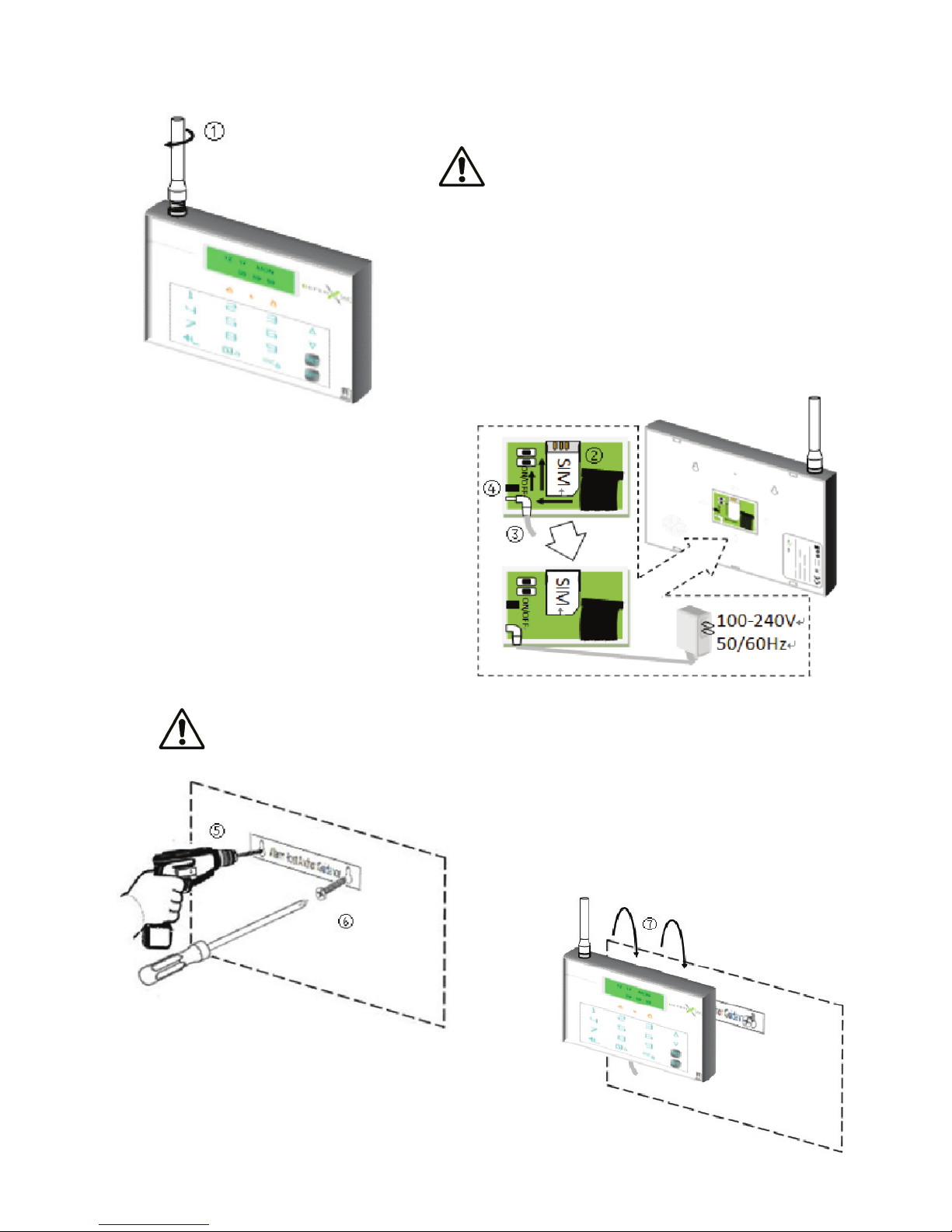
Main Alarm Host And Wireless Remote Keypad
1. Screw the antenna by hand onto the Main Alarm Host until rmly
attached
2. Carefully insert a valid GSM SIM card into the SIM Card Slot
located at the rear of the Main Alarm Host
3. Apply AC / DC power to the system with the
power adapter provided.
4. Turn on the battery switch located beside the
power connector.
5. Position the Alarm Host Anchor Guidance on
the desired mounting surface.
7. Position the Main Alarm Host onto the wall.
8. To install the Wireless Remote Keypad, repeat Steps 3 – 7.
NOTE: When selecting mounting location, avoid xing any unit onto or very close to metalwork
(i.e. radiators, water pipes, etc.) as this could affect the radio range of the device.
6. Drill two holes, insert wall anchors and fasten with the
two screws.

7
Your Quick Guide to DefenX360TM System Installations (Cont.)
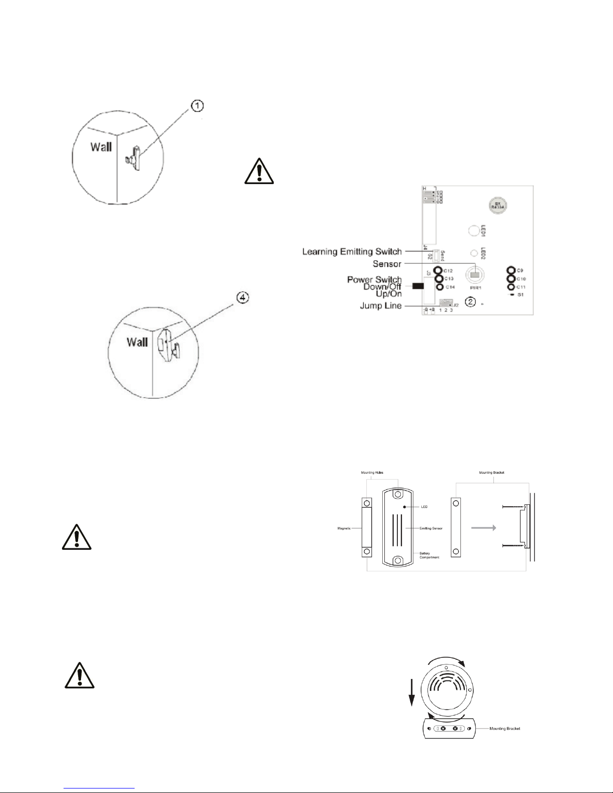
Wireless Wide-Angle PIR Sensor
1. Use the mounting bracket to mark two drilling holes in the corner of a
room mounted at a height of between 2 and 2.4 meters. Drill the holes
and t two screws provided to x the bracket.
NOTE: Do not drill the xing holes with the bracket in
position. The power tool may cause damages to the
bracket.
2. Undo and remove the screw located at the bottom
edge of the Sensor. Open the sensor shell to
set Jump Line to Position 2 – 3 for a detection
frequency of every 5 minutes.
3. Connect the battery supplied to the battery clip.
Ret the cover and xing screw.
4. Slide the PIR sensor into the bracket. Adjust the sensor to an angle that
the movement of an intruder would cut across the device.
5. Slide the power switch on the side to “ON” and the unit will enter into
the normal working state after 30 seconds.
Wireless Door Sensor
1. Slide off the battery cover and place the provided battery into battery holder with “ + ” facing upward and ret the
battery cover.
2. Attach the adhesive pads onto the back of the magnet and detector.
3. Mount the detector on the frame and the magnet on the opening
part at a height of at least 1.6 meters.
Indoor Siren
1. Plug the Internal Siren into a suitable indoor mains socket at a height above 1.8 meters.
NOTE: The magnet must be aligned on the LEFT side
parallel to the detector and within 10 mm to the sensor
when the door / window is closed.
Smoke Detector
1.Use the mounting bracket to mark two drilling holes on the wall. Drill the holes and t two screws provided to x
the bracket.
2.Remove the battery cover and connect the provided battery to the battery clip.
3.Ret the battery cover. Slide in the detector and rotate clockwise to lock the
detector onto the mounting bracket.
NOTE: Do not drill the xing holes with the bracket in position.
The power tool may cause damages to the bracket.

8
Your Quick Guide To DefenX360TM System Operations
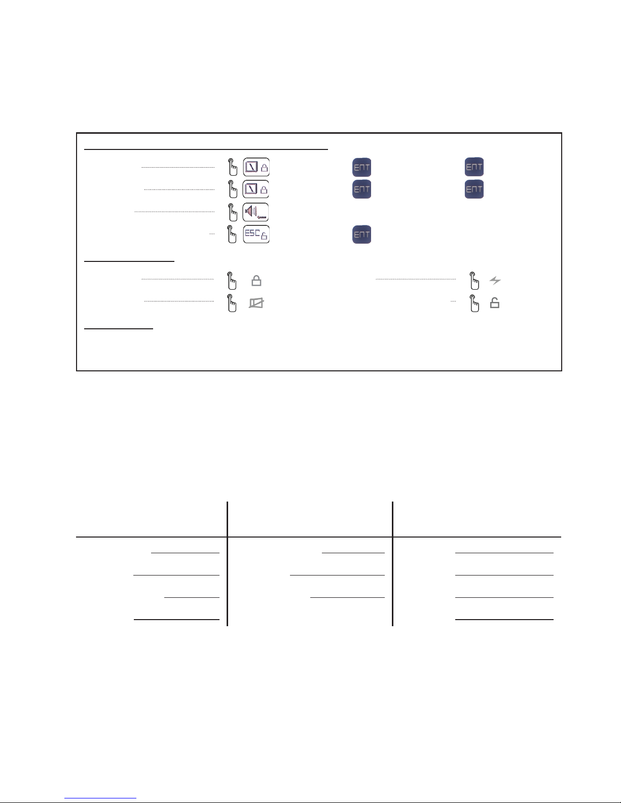
Key Buttons
Main Alarm Host And Wireless Remote Keypad:
Arming Away + Password* + + Armed Away +
Arming Home + Password* + + Armed Home +
Emergency
Disarming & Stopping Alarms + Password* +
Wireless Remote:
Arming Away Emergency
Arming Home Disarming & Stopping Alarms
Phone / SMS:
Includes stopping an alarm by telephone and remotely arming / disarming by telephone / SMS, please refer to
the “Securing The Protected Site” for more details.
* DefenX360TM Main Alarm Host employed a User Code (default: 888888) for “Arm”, “Disarm” and “Set”
operations. The Wireless Remote Keypad is double password protected and operates with a User Code (default:
111111) for “Arm / Disarm” and a Prog. Code (default: 888888) for “Set” operations. You are strongly advised to
change the Default Codes to Personal Codes IMMEDIATELY. See “Setting Your Passwords” for more details.
Emergency Contact List
Thank you for choosing DefenX360TM, the state-of-the-art LCD touchpad wireless alarm system for home and ofce
security produced by nnB. For future references, please note down the following information.
Dealer’s Details Call Center’s Details** Telephone Numbers*** Set On
Your DefenX360TM
Dealer's Name: Call Center's Name: Phone No.2:
Phone No.: Phone No.1: Phone No.3:
Person to Contact: Account Number: Phone No.4:
Serial No.*: Phone No.5:
* Located at the back of the Main Alarm Host.
** Phone No.1 on the system is for Call Center use (or Personal use if you are monitoring by yourself) and
Account Number is for the identication of your alarm system to the Call Center.
*** The telephone numbers that you programmed to be called when the alarm is triggered.

9
DefenX360TM Luminous Signal Indicators
Main Alarm Host
• On – No GSM network detected (or SIM card not available). Flashing – GSM detected.
Slow ash: 200ms on, 2s (3s for DX360Z & DX360ZL) off indicates the Main Alarm Host is in standby mode.
Fast ash: 200ms on, 600ms off indicates the Main Alarm Host is dialing the programmed numbers.
• On – Armed (Home or Away). Flashing – Smart sensor open detected. Off – Disarmed.
• On – AC connected (normal). Flashing – Working with backup battery. Off – Low backup battery.
Wireless Remote Keypad
• When the Main Host is armed as “Armed Home” mode, light will turn on together with the light.
• When the Main Host is armed as “Armed Away” mode, only light will turn on.
• On – AC connected (normal). Flashing – Working with backup battery. Off – Low backup battery.
Useful Hints For DefenX360TM Users
Stopping An Alarm
A triggered alarm can be stopped by + Password on the Main Alarm Host (default: 888888) or Wireless
Remote Keypad (default: 111111) or by using the Wireless Remote . To stop an alarm remotely, press the
“ *” button after receiving the call from your system, the system will remain Armed and the next number will not be
called. By SMS message, send a message “XXXXXXCF” to the Main Alarm Host. XXXXXX is your 6-digit User Code
on the Main Alarm Host. The system will be Disarmed and a conrming message will be sent.
Emergency, Perimeter and Motion Zones
Sensors set to the Emergency zone will trigger an alarm in Armed / Disarmed mode upon disturbance. Sensors
linked to the Perimeter zone can only trigger an alarm when the system is in Armed mode (Home / Away). Sensors
programmed to the Motion zone could only trigger an alarm in “Armed Away” mode.
System Testing
With the system in standby mode, user could trigger each sensor or accessory one by one. The triggered unit will be
shown on the Main Alarm Host without triggering an alarm.
SMS Reporting
By programming a private number to be the 1st caller number (Call Center Number) and if the upload status has
been enabled, you will be able to receive system information such as “Arm”, “Disarm”, Alarm or AC failure.
Telephone Alarm
If an alarm was triggered and providing a valid GSM SIM card is present, the system will automatically contact the
programmed telephone numbers in the system. Upon receiving the call, the recorded voice message is played
immediately for 30 seconds repeatedly. User has the following options:
Press “ 8” to enter into the listening status and hear the alarm background sounds for 20 seconds.
Press ” #” to play the recorded voice message again.
Press “ * ”, the Main Alarm Host will end the call and stop dialing the next Auto Dialer Number. The system will return
to “Arm” status.
Directly hang off the phone, the Main Alarm Host will end the call and automatically dial the next Auto Dialer Number.
Chime Function
By allocating a sensor to the Chime zone, whenever a sensor in that zone is triggered in the standby mode, the
system will produce a few “bi” sound to alert the user. Please refer to “Set Smart Zone” for more details.

10
Introduction
Overview
DefenX360TM series wireless GSM LCD touchpad alarm system is the state-of-the-art LCD touchpad wired / wireless
alarm system for home and ofce security. Its aesthetic design with a user friendly illuminated LCD menu and a
touchpad control provides a new standard of security alarm system and makes your home works in a Hi-Tech style.
You can install the system and monitor your home / ofce all by yourself or via a security center service with Ademco
CID protocol. DefenX360TM secures your property for you, while you enjoy your life.
NOTE: This manual is designed to familiarize you with the DefenX360TM security alarm system.
We strongly recommend you read the manual before using your system.
System Arming
Your DefenX360TM is controlled by a Main Alarm Host designed to collect data from sensors located within the
protected site. The system provides user with protection options of “Armed Home” and “Armed Away”. “Armed
Home” will arm all zones while the “Armed Away” will only arm the Perimeter zone. An alarm is triggered upon
detection of disturbance in any one of the armed zones. Sensors and detectors set to the Emergency zone could
also trigger an alarm regardless of the system is being armed or disarmed.
SMS Alert / Phone Call To Preset Numbers And Call Center
In the event of alarm being triggered, the system will automatically report the event via SMS alert (if GSM
is available) or phone call to the Call Center and preset telephone numbers in the dialing sequence until an
acknowledge signal is received.
User and Master Codes
DefenX360TM Main Alarm Host employs a 6-digit User Code for “Arm”, “Disarm” and “Set” operations. Wireless
Remote Keypad is double password protected and operates with a 6-digit User Code for “Arm” / “Disarm” and a
6-digit Prog. Code for “Set” operations. It is recommended that only the Master User has access to the programming
functions (“Set” operation) of the system and to the Main Alarm Host.
Zones
The system could monitor 31 wireless zones (supporting up to 124 wireless accessories) and 8 wired zones. Each
zone could be independently allocated into one of these types:
• Perimeter (Outer Zone Defense): Generally use for detecting area such as doors, windows, etc.; Wireless Door
Sensors and Wireless Curtain PIR Sensors are normally allocated into this zone.
• Motion (Inner Zone Defense): Generally use for detecting area such as living room, aisles and bedrooms etc.,
Wireless Wide-angle PIR Sensors and Wireless Door Sensors are normally allocated into this zone.
• Emergency: This zone monitors the system status for 24-hour and is usually used for emergency distress,
medical rescue, gas leakage, smoke and re alarm, etc. Sensors including Panic Button, Wireless Gas Sensors
and Wireless Smoke Detectors are normally allocated into this zone.
Bypass Zones
With the bypass sensor function, a zone could be omitted upon arming. Any sensors allocated to the bypassed zone
will not be protected and will not trigger an alarm.
Remote Phone And SMS Control
It is possible to gain basic control (Arming / Disarming the system) over the system by dialing into the system or
by sending a SMS message. You may also activate the microphone on the Main Alarm Host to Listen-In to what
is happening in the protected property. With a personal number set to the 1st Caller number and upload status
is enabled, an SMS notication message will be sent to the user to conrm a status change of the system when
conducted remotely.

Table of contents
Popular Security System manuals by other brands

EDM
EDM Solution 6+6 Wireless-AE installation manual

Highway Safety Group
Highway Safety Group EA401 user manual

Siren
Siren LED GSM operating manual

Detection Systems
Detection Systems 7090i Installation and programming manual

Se-Kure Controls
Se-Kure Controls MicroMini SK-4841 instructions

Siemens
Siemens FDM273 manual