
NELSEN WATER NRO ROC-3HE User manual

Nelsen NRO ROC-3HE
System Controller Documentation
Systems with 3 hp Motors and Above

2
Table of Contents
Table of Contents..................................................................................................................................................................................................................................................................Description Page
Specifications, Table 1......................................................................................................................................................................................................................................................................................................1
Schematic, Figure 1..............................................................................................................................................................................................................................................................................................................2
Field Wiring Diagram, Figure 1.1....................................................................................................................................................................................................................................................................3
Controller Overview, Figure 2...............................................................................................................................................................................................................................................................................4
Controller Detail: CPU-4..................................................................................................................................................................................................................................................................................................5
Controller Detail: TB-6.......................................................................................................................................................................................................................................................................................................6
Conductivity Probe Installation, Figure 5..........................................................................................................................................................................................................................................7
Controller Programming: Accessing Hidden Menus, Figure 6....................................................................................................................................................................8
System Start-up w/Permeate Flush..........................................................................................................................................................................................................................................................8
Controller Programming: Program Selections, Table 2.............................................................................................................................................................................................9
Controller Programming: Parameters Explained, Appendix A...................................................................................................................................................... 10-11
Controller Fault Displays................................................................................................................................................................................................................................................................................ 11-12
Controller Programming: Programming Interface Overview...................................................................................................................................................................... 13
Warranty.............................................................................................................................................................................................................................................................................................................................................. 14

1
Table 1 - Specifications
Inputs
Tank level switches (2) Normally-Closed. Can be used with a single level switch.
Inlet pressure switch Normally-Open.
Pretreat lockout switch Normally-Open.
High Pressure switch Normally-Open.
Controller Power 100-240 VAC, 60/50Hz (Switching power supply automatically adjusts)
Permeate Conductivity 0-3000 PPM, 0-6000 μs (standard sensor, CP-1, K=.75)
Feed Conductivity (opt) 0-3000 PPM, 0-6000 μs (standard sensor, CP-1, K=.75)
Output Relay Ratings (relays are fused with a 6A fuse)
Feed Solenoid 0.5A. Voltage is the same as motor/supply voltage.
Flush Solenoid 0.5A. Voltage is the same as motor/supply voltage.
Motor Contactor Coil 0.5A. Voltage is the same as motor/supply voltage.
Motor Contactor
ROC-2XHE-20 20A Definite Purpose Contactor: 3.0 HP @ 208-240V.
ROC-2XHE-40 40A Definite Purpose Contactor: 5.0 HP @ 208-240V.
Circuit Protection
Main/Relay Power Fuse F1 5x20mm 6 Amp Littelfuse 0234006P
Power Supply/CPU Fuse F2 5x20mm 0.125 Amp Littelfuse 0218.125P
Other
Dimensions 7” tall, 7” wide, 4”” deep. Nema 4X Polycarbonate Hinged Enclosure.
Weight 2.7 lb.
Environment 0-50°C, 10-90%RH (non-condensing)

2
Figure 1 - Simplified Schematic

3
Figure 1.1 - Field Wiring Diagram

4
Figure 2 - Controller Overview
Keypad
System ON/OFF,
Up Arrow
Down Arrow
Manual Run, Manual Flush
Supply Power
Connections
Motor
Connections
Terminal Board
CPU4 Board
Conductivity Probe
Connections
Display
(4 line, 20 character)
Clear, concise feedback
on the RO’s status.
Alarm
Display backlight
flashes along with
audible beeper to
indicate alarm condition.
5
Typical Configuration
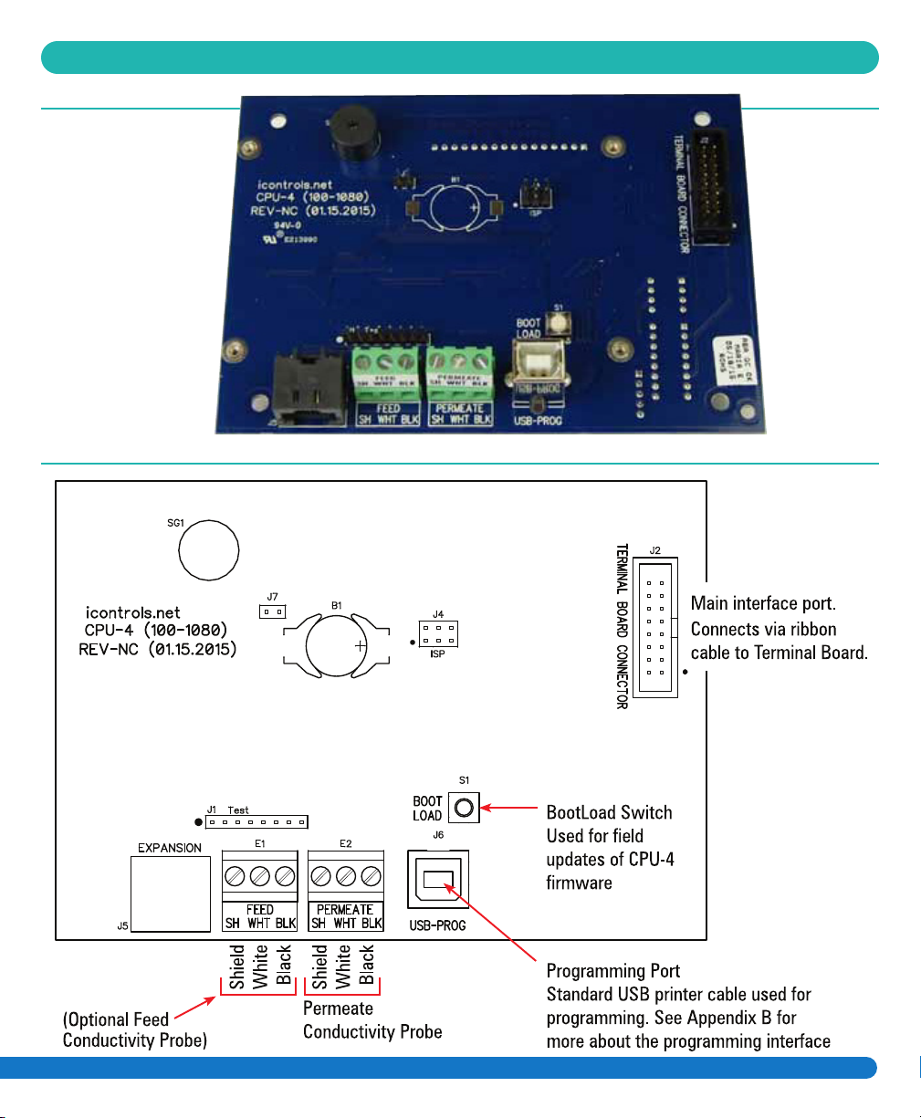
Figure 3 - Controller Detail: CPU-4
Typical Configuration

6
Figure 4 - Controller Detail: Terminal Board, TB-1 (See Fig. 1 for schematic)

7
Figure 5 - Conductivity Probe Installation
Install the Conductivity Probe in the “Run”
of a Tee or equivalent location. Orient the
probe so that air can not become trapped in
the area near the probe.
FLOW
FLOW
Conductivity
Probe

8
Figure 6 - Controller Programming: Accessing the Hidden Menus
System Start-up w/Permeate Flush
1 With the System ON, Press and
Hold the Up and Down Arrows.
2 With the Up and Down Arrows
depressed, Press the System On/Off
button. The menu will switch to the
RO Presets menu shown in Figure 7.
For systems equipped with a Permeate Flush, you must follow the procedure below for proper system start-
up. When there is no Permeate Water in the tank the RO will not start.
1. With the system on, Press and Hold the Up and Down Arrows
2. With the Up and Down Arrows depressed, Press the System On/Off button. This will switch to the
Hidden Menus as shown above.
3. If not already on the RO Presets Program, Press the Up or Down Arrows until you reach this screen.
4. Once on the RO Presets Program Screen, Press Manual to Edit this Screen.
5. Press the Up or Down Arrow to change to Program 2
6. Once on Program 2, Press Manual to Exit the screen.
Manual
Run/Flush
RO Presets Program 1
to change setting
Manual=Edit Sys=Save
RO Presets Program 1
for other menus
Manual=Edit Sys=Save
VALUES
1, 2, 3, 4
Save- Return to RO Display
System
On/Off
System
On/Off
Manual
Run/Flush
7. Press System On/Off to save the changes and return to the Home Page.
Once your Permeate Tank has filled enough to do a proper permeate flush, follow the steps again
changing from Program 2 back to Program 3.
This manual suits for next models
2
Table of contents
Other NELSEN WATER Controllers manuals

Popular Controllers manuals by other brands

Digiplex
Digiplex DGP-848 Programming guide

YASKAWA
YASKAWA SGM series user manual

Sinope
Sinope Calypso RM3500ZB installation guide

Isimet
Isimet DLA Series Style 2 Installation, Operations, Start-up and Maintenance Instructions

LSIS
LSIS sv-ip5a user manual

Rockwell Automation
Rockwell Automation 1769-L31 installation instructions


