
MS Sedco INTERSECTOR SDLC User manual

V0221-01-TC-0A-SDLC
USER’S GUIDE
INTERSECTOR™SDLC
MICROWAVE VEHICLE MOTION SENSOR
FOR USE WITH THE MS SEDCO INTERSECTOR HUB

V0221-01-TC-0A-SDLC MS SEDCO Page 2
IDENTIFICATION:
•Part Number: TC-0A-SDLC
•Product Name: INTERSECTOR™SDLC
•Software Compatibility:
oV3.2E: Intended for the INTERESECTOR SDLC or any Intersector that is being updated from V2.0F
oV3.1E: Intended for Intersectors being upgraded from V1.9U
DESCRIPTION
The INTERSECTOR SDLC is a microwave motion and presence tracking sensor designed for vehicle detection at
intersections. The sensor offers several advantages over inductive loop detectors and camera-based systems:
•Detection is not affected by weather conditions
•Immune to sunrise / sunset or post-rain glare
•Not susceptible to in-road breakage
•Multiple lanes can be covered by a single unit
•Lane by lane detection configuration ability
•Easily installs on corner signal poles and signal mast arms
•No privacy concerns
•Reduces construction cost
Through the INTERSECTOR HUB portal, the INTERSECTOR SDLC allows users to visually track vehicles as they approach
the intersection and allows easy setup of detection zones to provide programmable inputs to a traffic control cabinet.
The portal also provides the ability to verify system functionality.
SPECIFICATIONS

V0221-01-TC-0A-SDLC MS SEDCO Page 3
MOUNTING LOCATION –GUIDELINES
IMPORTANT NOTE:
MS Sedco recommends a “Pre-Analysis” be performed for the intersection where the INTERSECTOR SDLC is to be
installed. The Pre-Analysis provides key information that can be helpful with the initial setup of the sensor relative to
mounting height, distance from detection zone, number of lanes, etc. The information below helps to outline the
basic requirements to assist in the proper location and setup of the sensor.
1. Fundamental guidelines for installation:
Mounting height should be between 14 ft. and 20
ft. on a corner signal pole or on a mast arm no
further than 10 feet from the signal pole
The maximum offset angle (azimuth) to the
direction of traffic should be no more than +/- 15º
The sensor must be mounted level
Distance from the sensor to the Stop Bar should
not exceed 160 ft.
Distance from the sensor to the closest detection
zone should be at least 60 ft.
Typical detection range of the INTERSECTOR SDLC
is 600 ft.
The INTERSECTOR SDLC has a detection width
angle of 30 degrees. For best results the sensor
should be mounted at a tilt angle between
horizontal and 6 degrees downward plus or minus
the slope of the road.
2. Tilt angle (elevation) in degrees based upon mounting height vs. distance to front of the detection.
Keep in mind that the angle is relative to the slope/grade of the roadway.
MS Sedco recommends the use of an angle indicator for this procedure.
V0221-01-TC-0A-SDLC MS SEDCO Page 4
3. Approximations for quick reference:
Distance To Stop
Bar
Max. #
Lanes
Angle
Mounting
Mounting
Height
60 –80 Feet
2
-6
16 Feet
80 –100 feet
3
-6
17 Feet
100 –120 Feet
4
-4
18 Feet
120 –160 Feet
4
-2
19 Feet
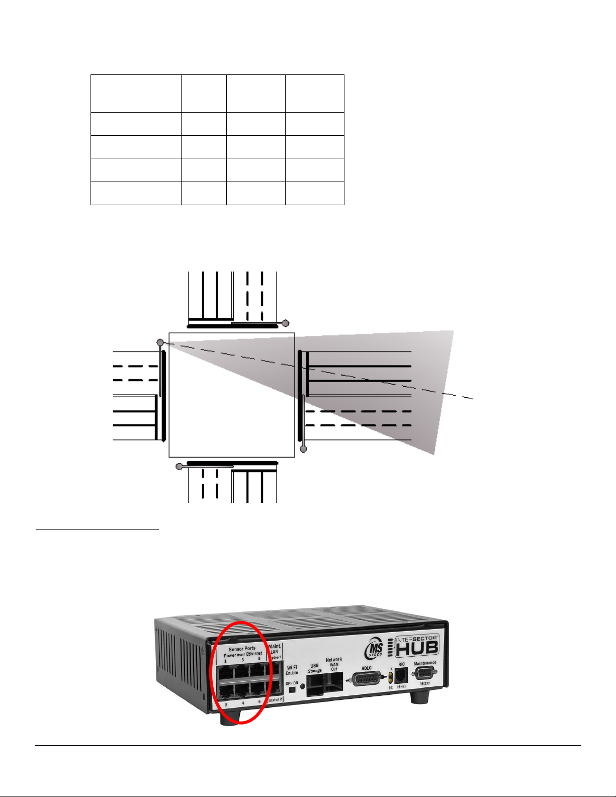
Use the gun-sights molded into the front and rear sensor covers of the INTERSECTOR SDLC
to help point the sensor at the center of the detection zone as shown below.
ELECTRICAL INSTALLATION
1. All power and data for the INTERSECTOR SDLC is accomplished through any of the 6 sensor ports provided at
the INTERSECTOR HUB. An ethernet cable with RJ45 connections must be plugged in at the back of the
INTERSECTOR SDLC and at one of 6 sensor ports. Power Over Ethernet (POE) is provided through the port.

V0221-01-TC-0A-SDLC MS SEDCO Page 5
2. If making the ethernet cable specific to the installation, adhere to the following cable configuration:
CONFIGURATION AND PROGRAMMING
Upon successful mechanical installation of the INTERSECTOR SDLC and cabling to the HUB, refer to the
INTERSECTOR HUB User’s Guide for complete programming and setup instructions.
TESTING & VALIDATION
Upon completion of all Intersector and HUB installation and setup procedures, all functions shall be tested to ensure
safe and reliable performance. As a minimum…
•Verify all devices have been properly secured
•Verify all wire connections and plug-ins are properly secured
•Ensure all defined settings and zones have been saved at the HUB
•Verify that each zone operates as expected per the configuration that has been defined
•Verify that the proper SDLC output shows up on the controller as vehicles go into each zone
•Ensure the Fail-Safe time (in seconds) is appropriate for the application
•Observe real-time traffic flow and ensure sensor and HUB performance is performing correctly
Clip is on opposite side
RJ45 Jack EIA/TIA 568B Std.

V0221-01-TC-0A-SDLC MS SEDCO Page 6
COMPATIBLE PRODUCTS
MS Sedco INTERSECTOR HUB
Part Number: TC-HUB
RMA PROCEDURE
Upon confirmation of a failed product, an RMA form must be filled out online prior to returning the
product to MS Sedco.
Go To: https://mssedco.com/return-repair-policy-form/
Or scan the QR code with your smartphone to go directly to the online form.
TERMS OF WARRANTY
MS SEDCO, Inc. guarantees this product to be free from manufacturing defects for five years from the date of original
invoice. If, during this period, the product fails to operate and has not been tampered with or abused, the unit can be
returned prepaid to the factory and be repaired free of charge or replaced, as determined by MS Sedco. After five years,
the unit may be repaired for a nominal service charge. No repairs will be made if the product is older than 8 years from
date of original invoice. The terms of warranty apply to the original buyer of the product and are not transferrable.
Limited warranty is in lieu of all other warranties, expressed or implied, including any implied warrantability of
merchantability. No representative or person is authorized to assume for MS SEDCO any other liability in connection
with the sale of our products. All warranties are limited to the duration of this written limited warranty. In no event shall
MS SEDCO be liable for any special, incidental, consequential or other damage arising from any unclaimed breach of
warranty as to its products or services. Terms of warranty are subject to change without notice.
COMPANY CONTACT
MS SEDCO Customer Service: custsvc@mssedco.com
7898 Zionsville Rd. Technical Support: techsupport@mssedco.com
Indianapolis, IN 46268 Website: www.mssedco.com
Phone: 317-842-2545
APPENDIX –GOOGLE MAPS
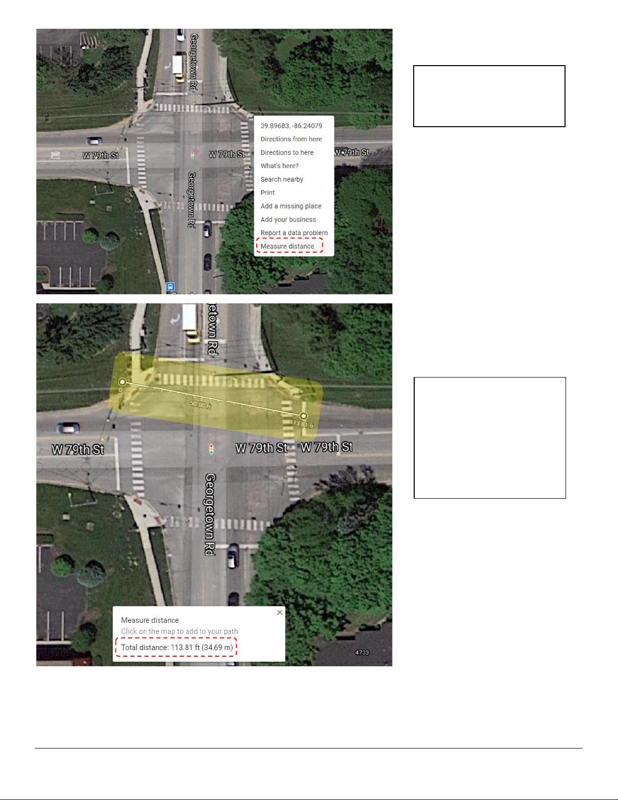
Google maps is a tool that can be used to help determine distances between key points such as the distance between
the Stop Bar and the INTERSECTOR SDLC mounting location. Open Google Maps and enter the location desired.
V0221-01-TC-0A-SDLC MS SEDCO Page 7
Once the location is
selected, right-click and
select “Measure distance”.
Follow instructions on
Google Maps to select
measurement points. The
result will be displayed on
the measurement line and
also in a dialogue box at the
bottom of the map.
Table of contents
Other MS Sedco Accessories manuals

MS Sedco
MS Sedco DH97 User manual

MS Sedco
MS Sedco MicroStar blue User manual

MS Sedco
MS Sedco DH100-CT User manual

MS Sedco
MS Sedco DH400 User manual

MS Sedco
MS Sedco ID20 User manual

MS Sedco
MS Sedco microStar User manual

MS Sedco
MS Sedco SmartWalk XP User manual

MS Sedco
MS Sedco INTERSECTOR User manual

MS Sedco
MS Sedco DH94D User manual











