Mentor radio M2115RCU Series User manual

Phone: (216) 265-2315 Fax: (216) 267-2915
www.mentorradio.com
1
Wireless Solutions for Advancing Communications
M2115RCU
RADIO CONTROLLER
OWNER’S MANUAL

Phone: (216) 265-2315 Fax: (216) 267-2915
www.mentorradio.com
2
Wireless Solutions for Advancing Communications
This owner’s manual applies to the following specific models:
AVIATION: M2115RCU-XXX
MARINE: M2115RCU-M
Mentor Radio produces a family of radio control units, also known as, Pilot Controlled Lighting (PCL),
or Pilot Activated Lighting (PAL) systems. This manual covers both aviation and marine band
versions for both the 25kHz and 8.33kHz channel spacing. The aviation band version is a VHF radio
that operates from 118-137MHz and the marine version is a VHF radio that operates in the frequency
range from 155-157MHz.
SAFETY
“Warnings” represent safety issues that if disregarded could cause serious injury or death to people.
“Cautions” represent safety concerns that if disregarded could damage equipment or cause personal
injury.
WARNINGS
This unit can be configured for operation from many different power sources. (10 to 30 VDC or
115 VAC or 230 VAC) Depending on the individual installation, dangerous voltages may be
present inside the unit’s printed circuit board mounting case. It is the user’s responsibility to
operate the unit safely for a particular installation.
1. High Voltage may be present inside the case when opened.
2. If installed outside, do not operate, test or power up the controller unit in the rain
with the NEMA enclosure opened and/or the case cover removed.
3. Maintenance of unit should be performed only by personnel qualified in electrical
safety.
4. Disconnect all electrical power prior to removing or performing maintenance on the
circuit board or on DIN rail mounted components.
5. Do NOT connect any external circuits rated with voltage higher than 230VAC to relay
contacts.
CAUTIONS
1. Do not connect electrical equipment to the controller with power applied.
2. When connecting the computer (PC) to the controller, ensure the power switch is
turned off.
3. Do NOT connect any input power other than that identified for the unit.

Phone: (216) 265-2315 Fax: (216) 267-2915
www.mentorradio.com
3
Wireless Solutions for Advancing Communications
Table of Contents
1. Safety Warnings 2
2. Component Layout 4
3. Controls Layout 5
4. Basic Features 6
5. Theory of Operation 7
6. General System Operation 7
7. Dip Switch Configuration Options 8
8. Installation 9
9. Testing, Programming and Adjustments 13
10. Periodic Maintenance 20
11. Troubleshooting 22
12. Schematics 25
13. Board Layout 30
14. Optional Accessories 31
15. Limited Warranty 32

Phone: (216) 265-2315 Fax: (216) 267-2915
www.mentorradio.com
4
Wireless Solutions for Advancing Communications
Component Layout
(Includes optional items)
AC Line Lightning Protector (opt)
Antenna Lightning Protector (opt)
Sensitivity Pot
DIN Rail with AC power plug
and CB's (opt)
Reset Switch Test Switch Communications Port
NEMA 4 Enclosure
(opt)
Phone: (216) 265-2315 Fax: (216) 267-2915
www.mentorradio.com
5
Wireless Solutions for Advancing Communications
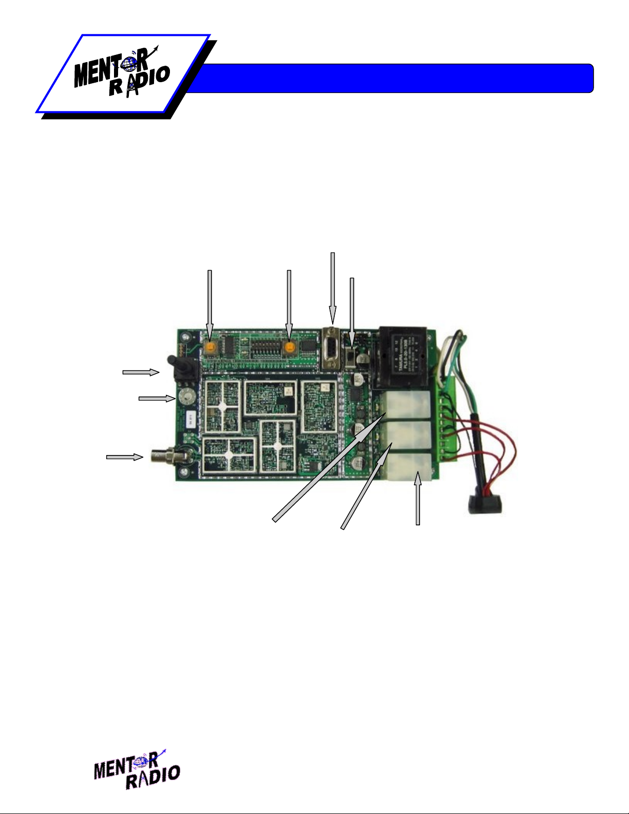
Controls Layout
Antenna
Input – BNC (6)
Sensitivity
Potentiometer (5)
Reset Button (1)
Power Switch (4)
Test Button
(2)
3 Click Relay (9)
5 Click Relay (8)
7 Click Relay (7)
Communications Port (3)
GND (10)

Phone: (216) 265-2315 Fax: (216) 267-2915
www.mentorradio.com
6
Wireless Solutions for Advancing Communications
Basic Features
Channel Spacing: 25kHz or 8.333 kHz
Synthesized Tuning - Customer programmable. Utilizing a standard DB-9 serial cable
(included) use your PC to program the operating frequency using custom PC software.
Password authentication required to change operating frequency for increased security and to
prevent inadvertent changes.
Indicator lights - Colored LED’s light up to display relay activation. A STATUS LED flashes
once per second to indicate normal operation. A WINDOW LED turns on to indicates a mic
click has been detected and the unit is waiting for more clicks. Relays can only be energized
with the WINDOW LED is on.
Relays reactivate after power restoration – Automatically energizes those relays that were
energized prior to the moment power was lost. If the power is restored the timeout period is
reset to a full timeout period.
Operates from wide range of power sources – The controller can operate with any power
from 10VDC, 12VDC, 24VDC, 30VDC, 115VAC, or 230VAC. Conversion from DC to AC
power sources requires sending the unit back to the factory for re-configuration. Remote
locations may find it convenient to power the unit from a solar panel with a battery back-up to
simplify remote installations.
Test Button - Test relays and controller circuits without radio inputs.
Reset Button - De-energize relays before timeout expiration.
8 Different Time Out Values - No timeouts, 10 seconds, 5, 10, 15, 30, 45 & 60 minutes.
Available in 8 and 12 hour timeouts intervals upon special request.
Optional Weatherproof Enclosure - Unit fits into a 12”x6” fiberglass enclosure with built-in
mounting capability.
Optional Lightning Protection - Available for both AC line input and antenna input.
Power Status - Indication built into the STATUS LED.
Receiver Sensitivity Adjustment - Potentiometer adjustment allows setting receiver
sensitivity within the range of about 1 uV to more than 10,000 uV.

Phone: (216) 265-2315 Fax: (216) 267-2915
www.mentorradio.com
7
Wireless Solutions for Advancing Communications
Theory of Operation
The M2115RCU radio control unit consists of a radio receiver and a microprocessor-based
decoder/controller assembly. The receiver detects microphone “clicks”—short radio transmissions
when a user presses the push-to-talk (PTT) switch on an external VHF radio. The decoder operates
relays according to the patterns of clicks. The receiver is based on the model M15
receiver/transmitter. Except for the oscillator circuit, the transmitter circuits are not installed; the
oscillator is used to generate a test signal to check operation of the receiver and decoder/controller
assembly.
The receiver is a frequency synthesized dual conversion super heterodyne. It contains two mosfet
dual-gate mixers. The first local oscillator is frequency synthesized and operates at 400 mHz above
the channel frequency. The second local oscillator operates at 455kHz. The filtered output of the
receiver’s diode detector is connected to the input of the decoder/controller board where it is digitized.
The click detection and relay control logic is performed by the embedded microcontroller. The
microcontroller software determines if the signal is a valid radio click. If a valid click is received the
controller opens a window for the configured time interval to allow more clicks to be received. The
controller responds to 3, 5 or 7 pulses within the “window” time and energizes up to three relays. The
relay contacts are connected to the terminal strip on the decoder/controller board for controlling lights
or other external electrical equipment. For protection, relay contact connections from the
decoder/controller to external load circuits may optionally pass through three 5-ampere fuses or
circuit breakers.
The optional antenna lightning protector includes a replaceable gas discharge tube. The AC line
lightning protector also includes an LED which is normally illuminated indicating that the line protector
is operating properly. This LED will remain on even when the unit is turned off.
General System Operation
In order for a pilot to turn on the runway lights, he first sets his radio to the channel frequency used by
the airport radio control unit (M2115RCU). He then briefly presses and releases his push-to-talk
(PTT) microphone switch to produce a sequence of short “clicks”. The first microphone “click” starts
the “window” timer, after which the operator has either 3 or 5 seconds to complete the desired
sequence; either 3, 5 or 7 clicks. On the first click, the microprocessor turns on the “WINDOW” LED,
starts a timer and waits for more pulses. Once the “WINDOW” timer expires, the “WINDOW” LED is
turned off and the received pulse count is reset. During the time the window is open, any additional
clicks are received, and the response of the unit is governed by the selection of the various dip switch
settings. If three pulses are received, the 3-click relay is energized. On the 5th pulse, the 5-click relay
is energized, and on the 7th pulse the 7-click relay is energized. All energized relays remain
energized for the configured timeout period. At the end of this timeout period, all relays deactivate.

Phone: (216) 265-2315 Fax: (216) 267-2915
www.mentorradio.com
8
Wireless Solutions for Advancing Communications
During any time-out period, another series of microphone clicks may be transmitted, decoded and the
corresponding relays are energized provided the relay “deactivate disable dip switch” (switch 5) is not
enabled. The configuration of the following sections define how the unit will perform.
Dipswitch Configuration Options
To aid in the configuration, there is a visual aid in the PC software included to allow viewing the
switches that are set and the interpretation of their behavior. The testing of this behavior can be
performed from either the controller or the PC.
Timeout Period (Dipswitch 1, 2, and 3)
The following chart determines the switch settings for the corresponding time out period.
Timeout Period
SW 1
SW 2
SW 3
No Timeout ON ON ON
10 Second OFF ON ON
5 Minute ON OFF ON
10 Minute OFF OFF ON
15 Minute ON ON OFF
30 Minute OFF ON OFF
45 Minute ON OFF OFF
60 Minute OFF OFF OFF
Window Time (Dipswitch 4)
Off - 5 Second Window
On - 3 Second Window
Relay Deactivate Disable (Dipswitch 5)
Off – Normal Operation
On – Enable Function
With this feature enabled the only way to de-energize energized relays is at the end of the timeout
period.

Phone: (216) 265-2315 Fax: (216) 267-2915
www.mentorradio.com
9
Wireless Solutions for Advancing Communications
Mutually Exclusive Configuration (Dipswitch 6 Off)
This mode is programmed to allow only one of the relays to be energized at any one time. For
example, as before, the first click starts the configured “Window” timer. (3 seconds or 5 seconds). If 3
clicks are received before the “Window” timer is expired this causes the 5-click and 7-click relays to
drop out. On a fifth click, the second relay will pull-in again, and on a seventh click the third relay will
pull-in again. In this way, a pilot can change the lighting or which loads are controlled, if desired,
without waiting for the end of the time-out period. A new time-out period will begin at the end of the 5
second window.
Mutually Exclusive Disabled Configuration (Dipswitch 6 On)
This is the normal operating mode. This allows the relays to all be energized during the timeout
period. When each new sequence of clicks is received the corresponding number of relays energizes
without de-energizing any other relays. For example, the 3-click relay stays energized upon the
receipt of the 5th new click at which time the 5-click relay energizes.
Click-Off Function Configuration (Dipswitch 7 On, 8 Off)
5 Click-Off Enabled Configuration (Dipswitch 7 Off, 8 Off)
This configuration is primarily suited for customers who only want to turn one set of lights or
equipment on and off. The normal configuration will not allow the user to manually de-energize the
relays once the timeout period is started. This 5 click off option allows that. If only the 3-click relay is
installed to control one item, the user can turn on the equipment with 3 clicks and turn off the
equipment by clicking 5 times.
7 Click-Off Enabled Configuration (Dipswitch 7 Off, 8 On)
This is the same configuration as the 5 click-off, except that it allows the use of 2 different relays to be
controlled and allow the pilot to manually turn off both with 7 clicks. .
Installation
Depending on which model M2115RCU you purchased, installation can vary. To protect your
investment, we recommend lightning protection for all models installed outdoors. The following
considerations apply to every M2115RCU model.

Phone: (216) 265-2315 Fax: (216) 267-2915
www.mentorradio.com
10
Wireless Solutions for Advancing Communications
Choose a proper site*: The M2115RCU may be installed either indoors or outdoors.
Considerations about antenna placement, power input availability and relay connection requirements
should be taken into consideration when selecting a suitable installation location. (*Note: See installation
instructions for each model listed for individual recommendations.)
NOTE: When the M2115RCU is mounted outside, a location should be selected so that the antenna
is not “shadowed” by buildings or other obstructions in the direction from which aircraft may approach.
For maximum radio range, mount the antenna as high as practical. For outdoor operation use, a
optional NEMA enclosure is required. Application of a waterproof sealant over external coaxial
connectors is recommended along with all electrical wires connecting between the internal relays and
external equipment.
Configuration: This step is only required if the unit is not configured at the factory or if changing the
configuration dip switches is required. Connecting a PC to the enclosed DB-9 serial communications
port will allow the user to change the operating frequency. NOTE: only authorized persons are
allowed to change the operating frequency in the computer program. Access to this functionality is
password protected. The PC software also allows the user to test the new dip switch settings before
physically changing the switches on the radio control unit. Once the relay performance is verified the
new switch settings are to be made permanent, click the button “Get Physical Dip Switch
Settings.”(NOTE: 8.333Hz channel spacing requires 2 software programs to set the functionality; one
for setting the frequency and the other to set the performance “dip switch” settings.) Both are included
on the CD that is included with each unit.
Testing: After configuration, test the controller using the “Test” button in the PC board.
Installation for each model M2115RCU is as follows:
M2115RCU-BNC
1. Choose a location where:
No metal or other conductive particles could come in contact with the printed circuit
board of the M2115RCU-BNC radio control unit.
No fluids could splash onto printed circuit board of the M2115RCU-BNC.
Unit will not be exposed to severe temperature changes. (near furnaces or air
conditioners)
2. Connect relay and power wires to green connector. If unit is configured for AC power,
connect your power ground to the plate ground stud.
3. Connect antenna to printed circuit board BNC RF connector using adapter (included).
This manual suits for next models
4
Table of contents
Popular Controllers manuals by other brands

Digiplex
Digiplex DGP-848 Programming guide

YASKAWA
YASKAWA SGM series user manual

Sinope
Sinope Calypso RM3500ZB installation guide

Isimet
Isimet DLA Series Style 2 Installation, Operations, Start-up and Maintenance Instructions

LSIS
LSIS sv-ip5a user manual

Rockwell Automation
Rockwell Automation 1769-L31 installation instructions


