LaserLine 862 User manual

GB 862TH - 862TL
INSURANCE APPROVED
MOTORCYCLE ALARM/IMMOBILISER USER GUIDE
cod.: ISUT862T
FILENAME: ISUT862T.P65
862
862
Motorcycle Alarm Systems

2
NO DANGER FOR USER DUE TO THE
RADIO FREQUENCY EXPOSURE!
These Laserline systems are manufactured from the highest quality components
to ensure a long trouble free operating life and comply with the British insur-
ance industry’s criteria for motorcycle security for Category MC1 product.
PRODUCTCOMPLIANCE
Laserline862TH/862TL-Combined Alarm/ImmobiliserMC1-MIRRC TestNo.TMC1-
177/1002
These instructions are intended to familiarise you with their simple operation.
Note: There are 2 versions of the 862T, the only difference between the units
are the internal inclination sensors. Depending on the mounting position of the
unit on the motorcycle, depends on the unit chosen by the installer.”H” is for
Horizontal mounting position and “L” is for Lateral mounting position.

3
OPERATING INSTRUCTIONS
You would have received from your installer two remote control handsets (see fig. 1) and have
been shown the location of the Status LED (fig. 2).
ARMING THE ALARM SYSTEM
Press button A of the remote control; arming is signalled by two
flashes of the indicator lights and two acoustic tones (excludable).
When the alarm has been armed the LED will illuminate
(pre-alarm time) and after 30 seconds will flash regularly (0.5
second ON and 2 seconds OFF). An alarm condition will not be
generated by the tamper or inclination sensors until the system
has been set for 30 seconds (pre-alarm time).
Note: using button Bwithin the pre-alarm time (30
seconds) it is possible to exclude the inclination sensor and/
or the siren for a setting period.
- Exclusion of the inclination sensor: press button B once, the
system confirms the programming with a single flash of the
indicator lights and a single acoustic tone (excludable).
- Exclusion of the siren: press button Btwice within 2 seconds,
the system confirms the programming with two flashes of the in-
dicator lights and two acoustic tones (excludable).
The functions will be reset the next time the alarm is
armed using the remote control.
DISARMING THE ALARM SYSTEM
Press button Aof the remote control; disarming is signalled by
one flash of the indicator lights and one acoustic tone (exclud-
able). If, during the armed period, the alarm did not sound, the
LED installed will extinguish (see “Alarm Trigger Signalling” - page 7).
fig. 2
fig. 1
B
A
C

4
PASSIVE ENGINE IMMOBILISATION
Engine will automatically immobilise 30 seconds after switching OFF the ignition key or
30 seconds after the alarm has been disarmed by the remote control, if the ignition has
not been switched ON. Passive immobilisation is signalled by three acoustic tones (Not
excludable).
When this function is active, switching ON the ignition key will cause the system to generate
brief and repeated acoustic tones, whilst flashing the LED. When this function is active, it is
not possible to start the engine. To cancel the passive engine immobilisation, turn the ignition
keyONandpressanybuttonontheremotecontrolOncewithin10secondsorenteryoursecret
remote code. If the passive engine immobilisation is not cancelled within 10 seconds of
switching ON the ignition key, the alarm will automatically arm itself and instantly sound an
alarm condition. If this occurs, press button A or enter your secret remote code to cancel the
alarm condition (with or without ignition key ON).
PANIC FUNCTION
Pressing button Bfor more than 1second will activate the siren and the indicator light
flashes for 15 seconds. To stop the panic feature prior to the 15 seconds, press any one of
the 3 buttons again on the remote control. This function is not available if the ignition is
switched on.
HAZARD FUNCTION
Pressing button Cwith the alarm disarmed and with the ignition key OFF, activates the
indicator lights to flash. To stop the indicator lights flashing press button C or put the
ignition key ON, otherwise the function is automatically limited to 4 minutes.

5
SELF TEST FUNCTIONS
During the pre-alarm time (30 seconds), the LED will remain constantly ON, allowing you to perform
silent testing and verify the correct function of the tamper and inclination sensors. At the end of the pre-
alarm time (30 seconds), the LED will flash regularly (0.5 second ON and 2 seconds OFF).
HOW TO SELF TEST THE FOLLOWING DETECTION FEATURES ON THE ALARM
The following features depend on the type of motorcycle and insurance criteria’s. Please consult your
alarm installer regarding the tamper detection applying to your motorcycle.
STANDARD INSTALLATION DETECTION
INCLINATION SENSOR
Arm the alarm by remote control; The LED will be constantly ON. Changing the orientation of mo-
torcycle will cause the LED to blink off for 1 second indicating that detection occurred.
IGNITION SENSOR
Arm the alarm by remote control; any attempt to start the motorcycle by switching on the ignition will
cause an immediate alarm condition.
SELF-POWER SENSOR
Arm the alarm by remote control; Removal of the alarm system fuse or disconnection of motorcycle
battery will cause an immediate alarm condition.
Note: For servicing of motorcycle battery, disarm the alarm before disconnecting battery. Reconnect-
ing the power to the alarm within 6 minutes, will cause the alarm to automatically enter into Garage
Function. Reconnecting the power to the alarm after 6 minutes, will cause the alarm to remain in the
disarm state.
SENSOR SELF-TESTING

6
OPTIONAL TAMPER DETECTION
SEAT SENSOR/SIDE PANEL, ETC.
Armthe alarm by remote control;The LED will be constantlyon, releasing the seat/sidepanel, etc. will
causetheLED to blink off for 1secondindicating that detection occurred. Note: A connecting
cable from the alarm may be attached to the base of the seat/side panel. This cable
has a connector to allow removal of seat/side panel and should always be recon-
nected when the seat/side panel is refitted. Failure to reconnect will mean the alarm
will not sense the seat/side panel being released. Ensure the seat catch/side panel
mount is kept clean and free from dirt and grease. When refitting seat/side panel,
ensure cable is not trapped or damaged. If the cable is not reconnected to the seat/
side panel the alarm will still operate normally except no detection of the seat/side
panel being released will occur.
SIDE STAND SWITCH
Arm the alarm by remote control; The LED will be constantly ON, releasing the side stand
will cause the LED to blink OFF for 1 second indicating that detection occurred.
GARAGE MAGNETIC/INFRA-RED SENSOR/S
Arm the alarm by remote control; The LED will be constantly ON, moving the magnet from
the contact switch/create body movement within the range of the infra-red sensor will cau-
se the LED to blink OFF for 1 second indicating that detection occurred.
NOTE: Every time the magnetic contact or the infra-red sensor sends an alarm signal, the
red LED on the sensor lights for 2 seconds. The sensors have a battery saving function.
After an alarm signal as been transmitted to the alarm by a sensor, the sensor is inhibited
for 30 seconds and it must not detect any variations (keep still or move away from the pro-
tected area), otherwise this time will be extended and the sensor will not emit any alarm
signal until a least 30 seconds have past without detecting.

7
ALARM TRIGGER SIGNALLING
FLASH CODES
If an alarm condition was generated whilst the system was armed, when the system is
disarmed the direction indicator lights will flash briefly (½ second) and an audible tone
(excludable) will be produced to indicate that an alarm condition has occurred. For 30
seconds after the system is disarmed and the ignition key is OFF, you can check the alarm
memory by looking at the LED installed on the motorcycle, you can determine which
sensor generated the last alarm condition. The LED will begin flashing and the repeated
sequence of flashes will identify the relative sensor:
Note: Turning the ignition key ON or rearming the alarm system will reset the flash code
memory and the LED, will extinguish.
VERY IMPORTANT
· When the ignition key is ON, it is not possible to arm the alarm.
· Inan alarm condition, the siren soundsfor30 seconds. At the endofthis period the system
will stop sounding completely or pause for 5 seconds if a sensor is still detecting.
· All sensors have a limit of 10 consecutive alarm cycles (In line with existing and proposed
European Noise Abatement Regulations).
LED Off: No alarm condition occurred.
1 Flash/Pause: Alarm condition generated by INCLINATION sensor.
2 Flashes/Pause: Alarm condition generated by SEAT/SIDE PANEL/SIDE STAND sensor.
3 Flashes/Pause: Alarm condition generated by IGNITION SWITCH sensor.
4 Flashes/Pause: Alarm condition generated by POWER SUPPLY sensor.
5 Flashes/Pause: Alarm condition generated by INFRA-RED/CONTACT GARAGE sensor.
FLASH CODES ALARM CONDITION GENERATED BY

8
INCLINATION SENSOR SENSITIVITY PROGRAMMING
The inclination sensor has two sensitivity settings, which are programmable by the remote control.
To change between Low and High settings (factory setting is high) proceed as follows:
1) Turn the ignition key ON.
2) Within 10 seconds press button Con first remote control and then press button C on
the second remote control.
The alarm will respond with:
3 brief (½ second)acoustic tones and 3 brief flashes of the indicator lights = sensitivity set on Low
Repeat the procedure (points 1 and 2) to reset to High sensitivity, the alarm will respond with:
3 long (1 second) acoustic tones and 3 long flashes of the indicator lights = sensitivity set on High
Note: If motorcycle is parked on a busy main road and false alarms occur, disarm alarm
and verify which sensor triggered an alarm condition by checking the flash code from the
LED. If it indicates the inclination sensor, re-program sensitivity setting to Low.
ARM/DISARM ACOUSTIC TONES PROGRAMMING
To exclude the acoustic arming/disarming tones (factory set to include), proceed as follows:
1) Turn the ignition key ON.
2) Within 10 seconds press button Bon first remote control and then press button B on the
second remote control.
The alarm will respond with:
2 brief (½second) acoustic tones and 2 brief flashes of the indicator lights = tones disabled
Repeat the procedure (points 1 and 2) to include the acoustic tone, the alarm will respond with:
2 long (1 second) acoustic tones and 2 long flashes of the indicator lights = tones enabled
SECRET REMOTE CODE PROGRAMMING
This function allows you to memorise your own secret disarm sequence , utilising a combination of the
3buttonsontheremotecontrol.Beforeyouprogramyoursecretremotecodesequenceensurethatyou
have your “Emergency Pin Code” (see HOW TO KNOW YOUR EMERGENCY PIN CODE) noted in
therearoftheseinstructions.Studytheexamplestohelpyoudecideonthetypeofcodedsequenceyou
wouldliketouse. Button Bcannotbeusedforyour first button in yourcodedsequence,thisis to avoid
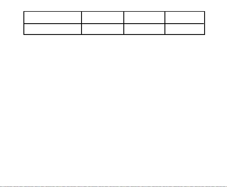
conflicts with the panic activation and inclination sensor/siren exclusion. Use the table or the table in
the rear of these instruction to note your coded sequence.
PROGRAMMABLE FUNCTIONS

9
Combinationsoflessthan3buttonsarealsoaccepted.To programthe “secretremotecode”,proceed
as follows:
1) Disarm the alarm system.
2) Turn the ignition key ON.
3) Press and hold button Cof a functioning remote control.
4) Turn the ignitionkey OFF whilstmaintaining the activation of button Con the remotecontrol. The
LED mounted on the motorcycle will illuminate.
5) Release button Cof the remote control.
6) Enter the desired sequence of buttons for the secret code. The sequence can be composed by a
combinationofthreebuttonsoftheremotecontrol;eachbuttoncanbepressedamaxiumof15times.
The LED will switch OFF each time a button is pressed.
7) After entering your coded sequence, turn the ignition key ON to exit the procedure.
Example 1: Cbutton pushed 5 times + Abutton pushed 1 time + Bbutton pushed 3 times.
Example 2: Cbutton pushed 3 times + B button pushed 2 time + Cbutton pushed 1 time.
Example 3: Cbutton pushed 5 times .
NOTE:
- The “secret code” sequence can be removed by executing the above procedure untill point 5;
afterwards turn the ignition key ON to exit.
- Todisarmthealarmduringanalarmcondition,firstlypressanyoneofthe3buttonsontheremote
control(thiswillstopthesirensoundingbutnotdisarmthealarm),thenenteryourcodedsequence.
- If you forget your secret code, disarm the alarm with your emergency pin code, after you disarm
the alarm, the alarm will automatically enter remote programming. Reprogramming all remote
controls will reset the system to a single press of button Afor disarming.
Number of presses
Button ” “Button ” “
Button ” “

10
Automatic Sleep Mode
Thealarmsystemincorporatesanautomaticsleepmodewhichconservesthechargeofthemotorcycle’s
battery whilst the motorcycle is not in use. This feature is activated automatically if the motorcycle is
notusedfor3consecutivedays(72hours).Inthismode,thealarmwillnotrespondtotheremotecontrols
and the LED will not flash. All sensors are still armed.
Garage Function
This function allows you to manually activate the sleep mode with only the immobilisation activated.
To activate this function proceed as follows:
1) Disarm the alarm system.
2) Turn the ignition key ON.
3) Press and hold button Bof a functioning remote control.
4) TurntheignitionkeyOFFwhilstmaintainingtheactivation of buttonBontheremotecontrol.One
long acoustictoneandonelongflashoftheindicatorlightswillsignaltheactivationofthe Garage
Function.
5) Release button Bof the remote control.
To “wake up” the alarm, simply turn ON the ignition key and press any button on a remote control or
enter the secret code within 10 seconds.
Wheneitherofthese functionsareactive,switchingONtheignitionkeywillcausethesystemtogenerate
brief and repeated acoustic tones, whilst flashing the LED. If a button is not pressed or the secret code
isnotenteredwithin10secondsthealarmwillautomaticallyarmandinstantlysoundanalarmcondition.
Ifthisoccurs,pressbuttonAorenterthesecretcodetocancelthealarmcondition(withorwithoutignition
key ON). When either of these functions are active, the current draw is less than 0.5 mA.
Note:
- Passive immobilisation is not affected by Automatic Sleep Mode or Garage Function and will still
be active under these conditions.
- If optional radio transmitting “infra-red garage sensor” or “garage door contact switch” are
BATTERY SAVING FEATURES
This manual suits for next models
2
Table of contents
Other LaserLine Car Alarm manuals

LaserLine
LaserLine 989E Install guide

LaserLine
LaserLine 996 kit User manual

LaserLine
LaserLine 290i2 User manual

LaserLine
LaserLine 211UK User manual

LaserLine
LaserLine 670T User manual

LaserLine
LaserLine 361 User manual

LaserLine
LaserLine 996 User manual

LaserLine
LaserLine 261K User manual

LaserLine
LaserLine 270UK User manual
Popular Car Alarm manuals by other brands

Federal Signal Corporation
Federal Signal Corporation Pathfinder Siren Series Installation and maintenance manual

Falcon
Falcon Predator XL3 Installer manual

Audiovox
Audiovox Auto Security XR91 Programming guide

Clifford
Clifford Sabre II owner's manual

CrimeStopper
CrimeStopper CS-8717 Wiring diagram

Ultra Start
Ultra Start 450 SERIES install guide