
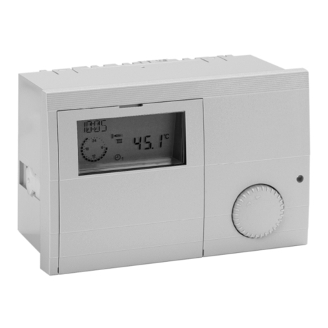
Kromschroeder Lago Basic 0101/1001 User manual

Lago Basic 0101/1001
Boiler module/Mixer
controller
Operating and
Installation Instructions
Please observe the safety instructions and
read through this manual carefully before
commissioning the equipment.

Safety information General information
2
General infor mation
Safety information
Power connection regulations
Please note the connection conditions specified by your local
electrical power supply utility and the VDE regulations.
Your heating control system may be installed and serviced on-
ly by appropriately authorised specialists.
E For fixed devices, a facility for mains disconnection in
accordance with EN 60335 must be installed in
compliance with the installation specifications
(e.g. switch).
EThe mains lines insulation must be protected against
damage caused by overheating (e.g. insulation hose).
EThe minimum distance to installation objects in the vicinity
must be chosen so that the permitted ambient
temperature is not exceed during operation
(see table - Technical data).
EIf the system is not installed properly, persons using it are
at put at risk of fatal or serious injury (electric shock).
Ensure the controller is de-energized prior to performing
any work on the controller!
Safety
Please read and keep in a safe place
Please read through these instructions carefully
before installing or operating. Following the installation, pass
the instructions on to the operator.
Warranty conditions
If the system is not installed, commissioned, serviced and re-
paired professionally, this will render the manufacturer's war-
ranty null and void.
Conversion
All technical changes are prohibited.
Transport
On receipt of the product, check that the delivery is complete.
Report any transport damage immediately.
Storage
Store the product in a dry place. Ambient temperature: see
Technical data.
Important text passages
!Important information is highlighted with an exclamation
mark.
EThis attention symbol is used to point out dangers in this
manual.
General Notes
!With regard to installation, operation, and maintenance,
the following instructions must be observed. This
device must only be installed by a specialist technician.
Improperly performed repairs can subject users to
considerable risks.

General information Description
3
!To comply with applicable regulations, the
instructions for assembly and operation must be
readily available at all times and must be handed
over to the responsible engineer when working on
the device for his attention.
Installation
Information on installation of the system is provided in Part
2 of this manual together with a connection diagram.
Description
Declaration of conformity
We the manufacturer declare the product Lago Basic
0101/1001 is in conformity with the fundamental require-
ments of the following directives and standards.
Directives:
– 2004/108/EC, 2006/95/EC
Standards:
– EN 60730-1, EN 60730-2-9
The manufacture is subject to the quality management
system in accordance with DIN EN ISO 9001.
General Function
Control of a fixed flow temperature or a fixed return
flow temperature via control of a heat generator or a
mixer.
It is possible to connect a room thermostat or a timer
switch (24 V).
Hot water function via sensor or thermostat.
Weather-dependent and room temperature dependent
control of a flow temperature via control of a heat
generator or a mixer
(time guidance only with additional module).
Heating module in a cascade

Description General information
4
General information 2
Safety information 2
Power connection regulations 2
Safety 2
Warranty conditions 2
Important text passages 2
General Notes 2
Installation 3
Description 3
Declaration of conformity 3
General Function 3
Operation 6
Explanation of the operating elements 6
Rotating switch 6
Incremental encoder / Shaft encoder 6
Key STL-test / Enter / Reset 6
Settings via DIP switch (rear side) 6
Display (normal mode "Run") 7
Symbols below the display 7
Starting up 8
Modifying set values 8
List of the User Set Values 8
Explanatory information 9
Set values 9
Settings via DIP switch (rear side) 11
Functions 12
Operation without operating module 12
Control of the flow temperature 12
Mode of operation cooling
(only as 1001 mixer operation) 13
Operation using operating module 13
Zone control 13
Warm-up temperature (HS min. – 5 K) 13
Frost protection function 13
DHW Relief 14
Circulation pump control
(not in the case of a fixed value) 14
Special functions 14
EEPROM check 14
Pump blocking protection 14
Mixer motor blocking protection 14
Delayed pump switch-off 14

General information Description
5
Installation 15
Assembly / Dismantling 15
Dimensions 15
Electrical connection Controller 16
Electrical connection, base 17
Options 18
System diagrams 19
Boiler controller with direct heating circuit and
Hot water 19
Boiler controller with Header pump / mixer motor
expansion 20
Boiler controller in cascade operation 22
Remote controls 23
The operating module Merlin BM, BM 8,
Lago FB 23
Remote control FBR2 23
Sensor resistances FBR 24
PC 24
Maximum delimiter 24
Telephone switch 24
Sensors 25
Outside sensor AF (AFS) S25
Immersion sensor KF (KFS) H/ SPF (SPFS) F25
Strap-on sensor VF (VFAS) v25
Sensor values / characteristic curve 26
Errors 26
Technical data 27
Glossary 27

Explanation of the operating elements Operation
6
Operation
Explanation of the operating elements
Rotating switch
RUN Automatic mode
To the left:
iStandby (frost protection only) KMBurner OFF,
heating circuit pump OFF, hot water function
OFF
MM: Mixer CLOSED, heating circuit pump OFF
x/jManual operation (emergency mode/service)
KM: Burner ON, heating circuit pump ON,
hot water charging pump ON
MM: Heating circuit pump ON
in the case of Prog. key => Relay test with in-
cremental encoder
BUS ID (boiler or heating circuit number)
To the right:
°CDwith room / outside sensor: Room set
temperature
°CDin the case of fixed value: Flow / Return flow set
temperature in the case of control mode:
Maximum flow temperature
Rbwith room sensor: Room sensor influence
Sbwith outside sensor: Heat slope
°C F/ vbKM: Hot water set temperature
MM: Mixer dynamics
Incremental encoder / Shaft encoder
Adjusting a set value
Key STL-test / Enter / Reset
STL-test (RT without effect) => By pressing > 1 sec
=>Burner on, for as long as key is pressed, display:HS-
Temp flashes (no function as mixer)
Enter (modify set values) => Selection of parameter for ad-
justment (flashing); Save by pressing again
=> for temperature readouts: Display set value (for 2 sec-
onds)
RESET : In order to reset the controller to the default set-
ting, keep the key pressed while defining the operating
voltage (display "EE")All user values will be lost during this
procedure! For this reason, please take a note of your own
parameters in this manual.
Settings via DIP switch (rear side)
!Settings 1 - 5 only take effect if used as control for a
heat generator (HS) when no corresponding
operating module is connected.
1 + 2: OFF,OFF=> No HS minimum delimiter
OFF,ON => Minimum delimiter when burner ON
ON,OFF => Minimum delimiter when heating
requirement
ON,ON => Minimum delimiter 24 h
3: Selection HS minimum delimiter HS minimum
temperature (40 °C <-> 60 °C)
4: Parallel operation OFF/ON
5: Antibacteria function OFF/ON
6: Sensor selection: 5 k NTC <-> 1 k PTC
Factory setting DIP switch 1 - 6 OFF

Operation Display (normal mode "Run")
7
Switch
9-stage
Key Incremental encoder
or shaft encoder
Display (normal mode "Run")
The display shows the flow temperature of the heat gener-
ator or the heating circuit. When the incremental encoder
is rotated, the following temperatures are displayed: 1.
Outside temperature (S, arrow 1),
2. Hot water temperature (F, arrow 2) => key: Set value
3. Room temperature(R, arrow 4) => key: Set value
Display „- -„ => No measured value available.
Symbols below the display
KM:
H// = Burner ON
F// = Charging pump ON
Z= HS pump ON // HC pump ON
= Communication OK!
MM:
H// = Mixer opens OPEN (arrow points upward)
F// = Mixer closes CLOSE
(arrow points downward)
Z= HC pump ON
= Communication OK!
If an arrow points towards one of the printed symbols, the
corresponding function is active.

Modifying set values Starting up
8
Starting up
Starting up
After the device has been properly installed (please ob-
serve the switch position on the rear side of your device),
switch on the power supply.
The software number for your device and then the index of
your software briefly appears in the display.
Then the readout appears in accordance with the position
of the rotating switch.
The controller is now operational => "Run"
Modifying set values
Rotate the selection switch to the corresponding set value
The display shows the currently set value.
Press the OK key.
The value starts to flash and can now be changed using
the rotary knob.
By pressing the button key OK once more, the value is
stored in the device.
Rotate the rotating switch to RUN Automatic mode
=> the mode is activated after 2 seconds.
List of the User Set Values
Designation Area Factory Values
Run => Normal mode
Display level with shaft encoder
- -
°C h= Room set tem
p
erature*
)
5
–
40 °C 20 °C
°CD= (MAX T-HS = 95 °C) =
in the case of fixed value =>
Flow / Return flow set tempera-
ture*)
in the case of control mode =>
Max. flow temperature*)
20 – 110 °C
40 °C
80 °C
Rb= Room sensor influ-
ence*)
00 – 20 10
Sb= Heat slope*) 0.0 – 3.0 1.2
°C F= only HS controller
Hot water set temperature*)
10 – 70 °C 60 °C
vb= only mixer controller
Mixer dynamic
05 – 25 12
BUS ID =>
KM: HS number
MM: Heating circuit number
--,00 - 08,11 - 88
01 – 15
--
01
x/jManual operation
(emergency mode/service)
Prog key = Relay test
00 – 03 00
iStandby
(OFF or only frost protection)
- -
*) !These values are set on the matching operating module (KM:
address 00/01; MM: address of mixer) if such a module is
connected.

Explanatory information Set values
9
Explanatory information
Set values
Room set temperature
Only effective if an outside sensor or a room sensor
(without operating module) is connected.
=> Setting the desired room temperature
Flow set temperature (fixed value)
Only takes effect if no outdoor sensor, room sensor, or
operating module is connected.
=> Input of the desired flow / return flow temperature.
Maximum flow temperature
If an outdoor sensor or a room sensor is connected
The measured temperature setting for the heating circuit
flow is limited to the maximum flow temperature setting
(overheating protection).
EThe heating circuit pump of the direct heating circuit is
switched off if the temperature of the heat generator
exceeds the maximum flow temperature by 8 K. The
heating circuit pump is switched on again when the
temperature of the heat generator drops below the
temperature [maximum flow temperature + 5 K].
Room sensor
Only active if a room sensor or the FBR analogue room
device (room sensor + selection of operating mode) is
connected..
The flow set temperature is increased by the set value
when the temperature drops below the required room tem-
perature by 1 K.
=> High values lead to fast control and large heat genera-
tor temperature fluctuations.
- - - - => pure weather-dependent control
0 => pure weather-dependent control *)
20 => pure room temperature control
*) Special function with ROOMS-INFL = 0
For one-off heating requirements during the night reduction
the heating pump continues to run until the next heating
period is reached (see chapter entitled "Circulation pump
control").
Heat-Slope
Only active if an outside sensor (without operating module)
is connected.. The gradient of the heat slope indicates by
how many degrees the flow temperature changes if the
outside temperature rises or drops by 1 °C.
Setting tip:
At cold outside temperatures, room temperature too low =>
Increase heat slope (and vice-versa)
At high outside temperature (e.g.16 °C) room temperature
too low => correction via set room temperature

Set values Explanatory information
10
0,2
0,4
0,6
0,8
1
1, 2
1, 5
2
2,5
3
20
40
60
80
10 0
201612840-4-8-12-16
Flow temperature [°C]
Outside temperature [°C]
Heat slope diagram (setting aid)
Setting 0 => Room control only
!The heat slope can best be set at outside
temperatures below 5 °C. The change in heat slope
setting must be made in small steps and at long
intervals (min. 5 to 6 hours) because the system
must first adjust to the new values each time the
heat slope is changed.
Guideline values
Underfloor heating S = 0.4 to 0.6
Radiator heating S = 1.0 to 1.5
Hot water set temp. (only in the case of boiler module)
Setting the desired hot water temperature. This tempera-
ture is stabilised in the storage tank for 24 h
HW thermostat instead of HW sensor: Hot water prepara-
tion in the event of short circuit on the sensor input.
If a corresponding operating device is connected the hot
water function is only activated during hot water enable
times.
Mixer dynamic (only in the case of mixer module)
Speed setting at which the mixer motor adjusts when a
control difference occurs. The control difference at which
the mixer motor opens/closes without interruption is en-
tered in Kelvin.
!Small values cause the mixer motor to adjust quickly
and can lead to oscillation.
BUS-ID (heating circuit number)
KM: [- -] HS with direct heating circuit and Hot water
[00] HS with header pump and Hot water
[01 - 08] [11-88] HS in a cascade with HS-Pump
=> Enter number of the heat generator. Setting > 08 can
be supported only during cascading by cascades with ap-
propriate cascade managers.
MM: The heating circuits are sequentially numbered start-
ing with "01". heating circuit numbers must not be assigned
twice. For replacement controllers, please enter exactly the
same heating circuit numbers as the replaced controller.
Table of contents
Other Kromschroeder Controllers manuals


Popular Controllers manuals by other brands

Digiplex
Digiplex DGP-848 Programming guide

YASKAWA
YASKAWA SGM series user manual

Sinope
Sinope Calypso RM3500ZB installation guide

Isimet
Isimet DLA Series Style 2 Installation, Operations, Start-up and Maintenance Instructions

LSIS
LSIS sv-ip5a user manual

Rockwell Automation
Rockwell Automation 1769-L31 installation instructions


