Invision IQeye Sentinel Series User manual

1
IQeye Sentinel™ Series
Indoor/Outdoor Camera
Installation and Operating Instructions

2
Contents
1 Unpacking ……………………………………………………….......…………….
2 Service …………………………………………………………………............….
3 Description …………………………………………………..................………
4 Installation …………………………………………………………………......….
5 Parts List …………………………………………………........………………….
6 Camera Fittings ……………………………………………….......…………….
7 Mounting Options ……………………………………………………....……….
8 Camera Arm Removal …………………………………………………......….
9 Mounting the Power Data Back Box ……………………………………...
10 Terminating Power and Data Cabling Inside The Back Box ….......
11 Camera Arm Installation ………………………………........…………….
12 Adjusting / Removing the Sunshield ………………………......……...
13 PC Configuration of IQeye Sentinel ……………………………...........
14 Camera / Lens Adjustment / Remote Back Focus ………......…...
15 Warranty ……………………………………………………………………........
3
3
4
4
5
5
6
6
7
8
10
12
13
15
19

3
1 Unpacking
Unpack carefully. This is an electromechanical device and should be
handled carefully. Check to ensure the following items are included:
>Integrated Sentinel camera/housing unit
>3 mm Allen wrench
>Wall mount template
>CD-ROM
>Punch down tool
>Mounting hardware
>Optional Heyco fittings
2 Service
If the unit needs repair service or parts, the customer should contact
IQinVision for authorization to return, as well as shipping instructions.
IQinVision
33122 Valle Road
San Juan Capistrano, CA 92675-4853
Phone: +1-949-369-8100 or 1-877-850-0805 (toll-free in U.S.)
Fax: +1-949-369-8105

4
3 Description
The Sentinel is a full featured, multi-megapixel H.264 Main Profile
all-weather camera. With support for up to 5MP resolutions, this next
generation camera provides multiple, individually configured H.264 and
simultaneous MJPEG streams. Designed with the installer in mind,
innovative features drastically reduce installation costs and time:
- The remote back focus feature greatly reduces installation time using the One-
Touch Focus feature for sharp images, and allows fine focus adjustments from
a remote computer eliminating the need for manual focus adjustments at the
camera.
- Ethernet terminal punch-down eliminates the need to terminate with an RJ45
connector.
- Steel camera hangers allow the installer to work with both hands.
In addition, the wall, ceiling, parapet options, rugged aluminum
construction, and IP66 weather resilience allow the camera to be
installed in almost any harsh environment. At less than 7W power
consumption, the Sentinel can be operational using Power-over-
Ethernet.
4 Installation
NOTE: This manual describes how to install the IQeye Sentinel Series camera system, and details the
wall, ceiling and parapet mounting options. Installations should be performed by qualified service
personnel only in accordance with local codes.

5
5 Parts List
The following depicts the parts included (Figure 1):
1. Indoor / Outdoor Camera and Lens Module
2. Wall, Ceiling & Parapet Arm
3. Power / Data Back Box
Tools required:
3 mm Allen wrench (supplied)
Small straight-blade screw driver
Punch down tool (supplied)
6 Camera Fittings
The IQeye Sentinel cameras are shipped with Heyco Liquid Tight snap-in
plugs (#4014) that are factory installed into the back box. These plugs
are rated to IP67 and can adequately seal cable diameters that range
from 3-5 mm (0.12-0.2 in).
For larger cables, like CAT5, it is recommended to replace the factory
installed plugs with the optional Heyco Liquid Tight fittings (#3207) that
are included in the accessory kit. These fittings are appropriate for cable
diameters that range from 2.90 mm (0.114 - 0.250 in). Please visit
www.iqeye.com/faq for details on using these optional cable fittings.
Figure 1
2
3
1

6
7 Mounting Options
8 Camera Arm Removal
NOTE: The camera/arm needs to be removed from the back box to allow the back box to be mounted to
the designated mounting wall, ceiling, or parapet surface.
1. Using the Allen wrench (supplied) loosen the 4 screws located on the
corners of the power/data back box.
2. Unplug the two camera-side connections from the back box (Figure 3).
3. Remove the camera/arm module from the back box.
Figure 2
Wall Mount Ceiling Mount Parapet Mount
Figure 3

7
9 Mounting the Power / Data Back Box
Before mounting the power / data back box, determine if the camera installation
will be wall, ceiling, or parapet and if the wiring will pass through the
compression fittings in the back or the ½” NPT conduit mount on the bottom of
the back box.
NOTE: If using the compression fittings in the back, it is recommended to replace the factory installed
hole plugs with the optional Heyco Liquid Tight fittings (#3207) from the accessory kit where larger
cables like CAT5 will be used.
NOTE: If using the ½” hole on the bottom of the junction box, a ½” (15 mm) NPT compression fitting
can also be used. (Heyco P/N 3200 is also appropriate).
1. As the arrows (Figure 4) indicate, use the supplied wall mount template to
locate the four mounting holes for the power/data back box.
2. Drill four (4) holes for the mounting screws using the included mounting
template as a guide. If installing outdoors, apply a weatherproof sealant
around each hole at the mounting surface.
3. Provided are four (4) #14 x 2” flanged (approximately 10 mm head x 50.1 mm
in length), hex head screws that can be used to install into a variety of wood
and metal substrates. If mounting into wooden studs, it is recommended that
a 1/8” (3 mm) wide by 2” (4.8 cm) deep pilot hole be drilled prior to installing
the screws. Alternatively, the installer can provide screws with a head
diameter less than #14 (3/8” or 10 mm) in size so that they can fit into the
junction box opening.
NOTE: It is recommended that each screw and the material it is being installed into be able to bear a
minimum of 50 pounds (22 kilograms) of pull force.
4. Pass the power and data cables through the back box, then install the power /
data back box on the mounting surface.
Figure 4

8
10 Terminating Power and Data Cabling Inside the Back Box
Power and data cabling must be routed to the right side (wall-side) of the back
box. Cut all cables with sufficient slack to reach the connector terminals in the
back box but not long enough to be pinched or obstruct the arm installation.
Figure 5
Camera-Side Terminations
Wall-Side Terminations
- RJ-45
- PunchDown Terminal
Screw Terminal
- Direct Power – 12-24VDC or 24VAC
- Trigger In
- Relay Out
9
1. Connecting Power:
The IQeye Sentinel can be powered via Ethernet using an IEEE 802.3af power
source, or powered directly.
- Powered via PoE: Input from conforming IEEE 802.3af Power-over-Ethernet (PoE)
power injector or switch.
- Powered Directly: Input voltage is 12-24V DC or 24V AC. IQeye Sentinel camera/
housing modules include built-in bridge rectifier circuitry, so power wiring polarity
can be installed with the + or - on either terminal without risk of damaging the camera
or affecting performance.
NOTE: Using a power source with specifications other than those defined herein may result in errant
functionality or damage to the camera, and will void the product warranty.
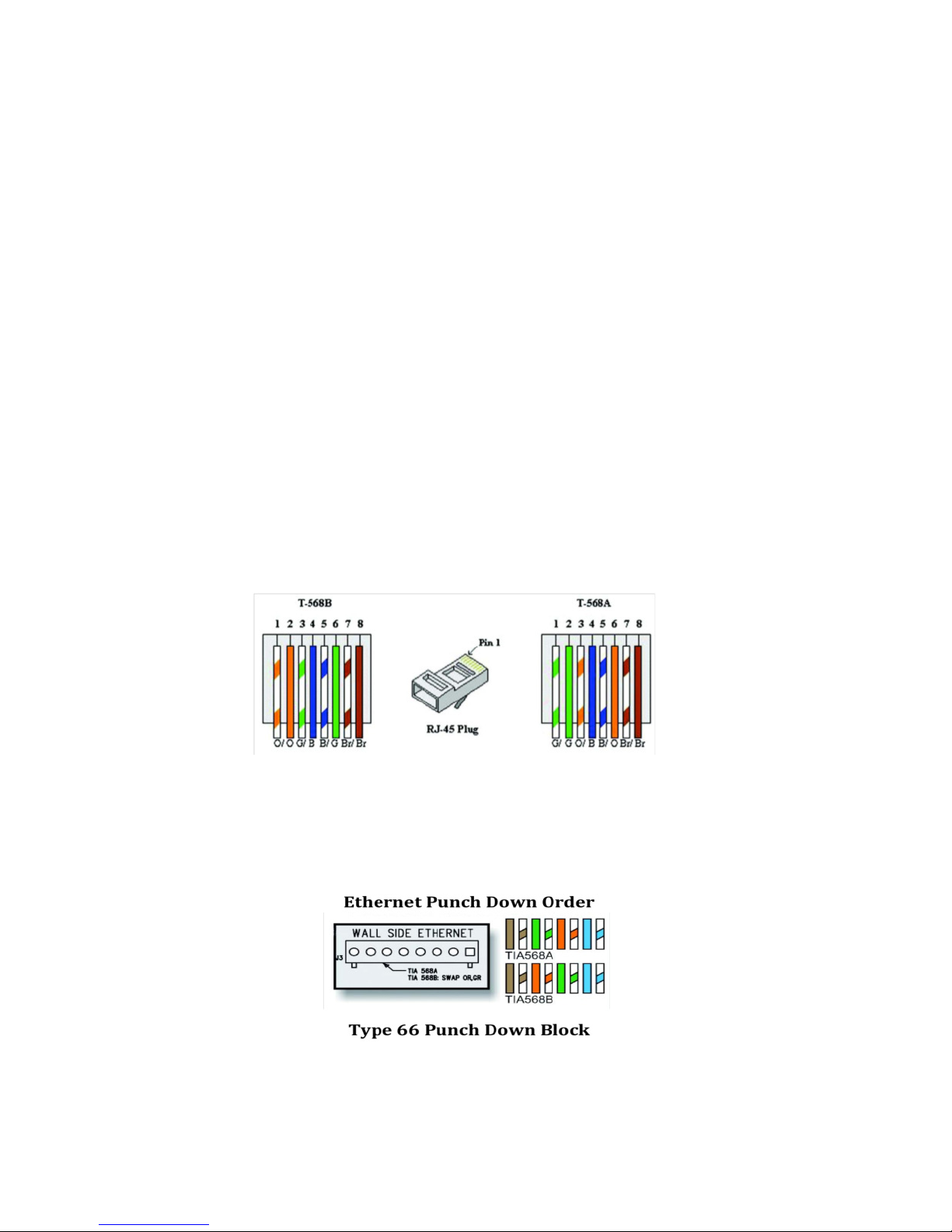
2. Connecting Data (Ethernet) Cable:
Route and connect the Ethernet cable to the Ethernet connections (RJ-45 - Figure 6
or Punch Terminal - Figure 7) labeled wall-side in the back box.
The two most common schemes for wiring CAT5 cables are 568A & 568B. The
568B wiring scheme is widely used in the US, and for off the shelf CAT5 cables.
New installations should use the 568A CAT5 wiring scheme. It is important that the
standard selected matches the building wiring.
Figure 6
Figure 7

10
11 Camera Arm Installation
The back box is provided with arm hangers on both sides to hold the camera/
arm module on the back box to facilitate installation. (Figure 8)
NOTE: The arm hangers function perfectly at any orientation of the junction box and will firmly hold
the camera and junction box cover in any of the wall, ceiling, or parapet mount configurations.
1. Insert the two (2) pins into the channel and slide the camera / arm module
down until it locks in place on the arm hanger.
WARNING: Serious injury and / or damage to the unit can occur if the camera / arm module is not fully
locked in place.
2. Connect Ethernet and terminal block cables from the camera to the left side
(camera side) of the junction box.
3. If I/O connections are being used, attach them to the appropriate I/O
terminals on the center terminal block of the back box (Figure 9).
4. After all connections are made in the back box, remove the camera / arm
hanger and secure to the back box by tightening the four (4) screws with the
supplied Allen wrench (Figure 10).
Figure 8
Figure 10
Figure 9
Table of contents


