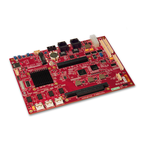
ICP Electronics ROCKY-512 User manual

December 25, 2003
©Copyright 2003 by ICP Electronics Inc. All Rights Reserved.
ROCKY-512
Version 2.1
StockCheck.com

2
Copyright Notice
The information in this document is subject to change without prior
notice in order to improve reliability, design and function and does
not represent a commitment on the part of the manu-facturer.
In no event will the manufacturer be liable for direct, indirect,
special, incidental, or consequen-tial damages arising out of the use
or inability to use the product or documentation, even if ad-vised of
the possibility of such damages.
This document contains proprietary information protected by
copyright. All rights are reserved. No part of this manual may be
reproduced by any mechanical, electronic, or other means in any
form without prior written permission of the manufacturer.
Trademarks
ROCKY-512 is a registered trademark of ICP Electronics Inc. IBM PC
is a registered trademark of International Business Machines
Corporation. Intel is a registered trademark of Intel Corporation.
Other product names mentioned herein are used for identification
purposes only and may be trademarks and/or registered trademarks
of their respective companies. If you have any question or need
other information, please connect to our web site.
http://www.ieiworld.com.tw
StockCheck.com

Table of Contents
CHAPTER 1. INTRODUCTION................................. 4
1.1 SPECIFICATIONS ............................................................5
1.2 PACKAGE CONTENTS .......................................................7
CHAPTER 2. INSTALLATION.................................. 8
2.1 ROCKY-512 BOARD LAYOUT.............................................8
2.2 UNPACKING PRECAUTIONS...............................................11
2.3 WATCHDOG TIMER SETTING (JP5).....................................11
2.4 COMPACT FLASH SETTING (JP3) .......................................12
2.5 COM2 SETTING ..........................................................12
2.6 CLEAR CMOS SETUP (JP1/1,3,5) ....................................13
2.7 DISKONCHIP™FLASH DISK MEMORY ADDRESS SETTING (U23) ..13
CHAPTER 3. CONNECTION................................... 15
3.1 VGA CONNECTOR (CN17)..............................................15
3.2 EXTERNAL SWITCHES AND INDICATORS (CN13).....................15
3.3 EXTERNAL POWER CONNECTOR (CN16)...............................16
3.4 ATX POWER CONNECTOR (CN15, CN14)............................16
3.5 LAN RJ45 CONNECTOR (CN12).......................................17
3.6 USB PORT CONNECTOR (CN11).......................................17
3.7 COMPACTFLASH CONNECTOR -- TYPE II (CN9).....................18
3.8 E-IDE HARD DISK CONNECTOR (CN10) .............................19
3.9 SERIAL PORTS (CN3, CN4) ............................................19
3.10 KEYBOARD &PS/2 MOUSE CONNECTOR (CN5, CN6)..............21
3.11 IRDA INFRARED INTERFACE PORT (CN7).............................21

StockCheck.com

2
3.12 PARALLEL PORT (CN8) ..................................................22
3.13 FLOPPY DISK DRIVE CONNECTOR (CN1)..............................23
3.14 DIGITAL I/O (CN2)......................................................24
CHAPTER 4. AWARD BIOS SETUP........................ 25
4.1 GETTING START ...........................................................25
4.2 STANDARD CMOS SETUP ...............................................26
4.3 BIOS FEATURES SETUP..................................................28
4.4 CHIPSET FEATURES SETUP...............................................29
4.5 POWER MANAGEMENT SETUP............................................30
4.6 PNP /PCI CONFIGURATION ........................................31
4.7 LOAD BIOS DEFAULTS ...............................................32
4.8 LOAD SETUP DEFAULTS .............................................33
4.9 INTEGRATED PERIPHERALS........................................34
4.10 PASSWORD SETTING ................................................34
4.11 IDE HDD AUTODETECTION.........................................35
4.12 SAVE AND EXIT SETUP ..............................................36
4.13 QUIT WITHOUT SAVING .................................................37
CHAPTER 5. SVGA SETUP .................................... 38
5.1 INTRODUCTION............................................................38
5.2 FURTHER INFORMATION ..................................................39
CHAPTER 6. PCI BUS ETHERNET INTERFACE....... 40
APPENDIX A. WATCHDOG TIMER........................ 41
APPENDIX B. I/O ADDRESS MAP ........................ 43
StockCheck.com

3
B.1 SYSTEM I/O ADDRESS MAP..................................................43
B.2 DMA CHANNEL ASSIGNMENTS ...............................................44
B.3 INTERRUPT ASSIGNMENTS....................................................44
B.4 1ST MB MEMORY MAP.........................................................45
StockCheck.com

4
Chapter 1. Introduction
ROCKY-512 is designed for limited space applications with only the
half size. It supports the full functions of an AT& ATX-compatible
industrial computer on a single board. So it provides wake on LAN
and Modem. The ROCKY-512 is equipped with a low-power
consumption and high performance GXLV/GX1 processor on board.
It also contains an SDRAM DIMM socket that can support up to 256
MB memory.
The ROCKY-512 provides an Ethernet interface, Compact Flash Type
II, EIDE interface, one parallel port, Two RS-232 serial ports, and a
PS/2 keyboard/mouse interface. The built-in SVGA CRT only. CRT
resolutions supports up to 1280 x 1024 @ 256 colors &1024x 768 @
16 bpp. The Flash ROM contains both the system BIOS and the VGA
BIOS. Reprogramming the Flash ROM could do modification, in
case of necessary.
StockCheck.com

5
1.1 Specifications
zNS GXLV/GX1-233/266/300 MMX 32-Bit x86 Processor
9Supports Intel MMX instruction set extension for the
acceleration of multi media applications
916 KB unified L1 cache
9Five-stage pipelined integer unit
9Integrated Floating Point Unit(FPU)
zSystem Memory: On board 64/128MB SDRAM and one
168-pin DIMM socket that supports up to 256MB SDRAM
memory
zBIOS: AWARD 256 KB Flash memory
zDisplay Controller
9MediaGx processor has applied UMA technology, which
provides 1.5~4MB display memory, configured through
BIOS setting.
9Support CRT only.
9Support non-interlaced CRT monitors resolutions up to
1280x1024 @ 256 colors &1024x768 @ 16bpp
zIDE Interface: The IDE support to two PCI Enhanced IDE hard
drives
zFDD Interface: Support up to two floppy disk drives, 5.25”
(360KB and 1.2MB)and/or 3.5”(720KB, 1.44MB, and 2.88MB)
zSerial Ports: Two RS232 ports. (Support wake on modem)
zParallel Port: One Parallel port, supports SPP/EPP/ECP mode
zPS/2 Mouse/Keyboard Connector: A 6-pin mini-DIN
connector for easy connection to a keyboard and PS/2 mouse
zUSB Interface: Two USB ports, USB 1.0 compliant
zPower Management: Supports power saving modes including
Normal/Doze/Sleep modes. APM1.1 compliant
StockCheck.com

6
zWatchdog Timer: Can be set to 1-255 seconds per period.
Reset or NMI was generated when CPU did not periodically
trigger the timer.
z10/100Mbps Ethernet Controller:
9Realtek 8100 IEEE802.u 100 BASE-TX standard Dual
Auto-sensing interface to 10MBps or 100MBps networks.
9On board RJ45 connectors provide for easy connection.
(Support wake on LAN)
zCompactFlash Disk:
9The CompactFlash Storage Card also runs in True IDE
Mode that is compatible with an IDE disk drive.
9It can be used with a passive adapter in a Type II socket.
zDiskOnChipTM Flash Disk:Supports one 32-pin socket for
DiskOnChip Flash Disk
zPower Supply: +5V @1.8A(typical)(+5V only)
zOperating Temperature: 0-60℃
zDimension: 7.27”(L)x4.85”(W)(185mmx122mm)For detail
dimension, please refer to page 8.
StockCheck.com

7
1.2 Package Contents
Before you begin installing the product, please check that all of the
following materials are included in the package:
zOne ROCKY-512 All-in-one single board computer
zOne CD disk for utility and drivers
zOne 3.5" IDE flat cable (40-pin to 40-pin 2.54mm pitch)
zOne serial + parallel port cable with bracket
zOne floppy cable (for 3.5" FDD only)
zOne 1 to 2, 6pin mini Din Connector for keyboard and mouse
If any of these items are missing or damaged, contact your
distributor or sales representative immediately.
StockCheck.com

8
Chapter 2. Installation
This chapter is guidance to assist you setup ROCKY-512 hardware,
including directions of setting jumpers and connecting peripherals,
switches and indicators. Before installation, please pay attention to
the unpacking precautions on the following page to ensure safety.
2.1 ROCKY-512 Board Layout
(Please turn to the following pages for layout diagram.)
StockCheck.com
Table of contents
Other ICP Electronics Single Board Computer manuals

ICP Electronics
ICP Electronics NOVA-7896 User manual

ICP Electronics
ICP Electronics ROCKY-P218BXA Pentium II & Creative Sound User manual

ICP Electronics
ICP Electronics Celeron ROCKY-3701 User manual

ICP Electronics
ICP Electronics ROCKY-3722EVS User manual

ICP Electronics
ICP Electronics ROCKY-P288EV User manual