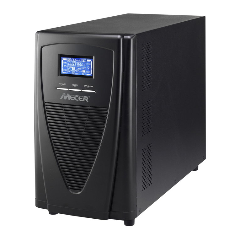
Gtec ZP120LCD User manual

-1-
USER’S MANUAL
MANUALE UTENTE
For Models ZP120LCD
1~3KVA
Unin errup ible Power Sys em

-2-
CONTENT
1. SAFETY AND EMC INSTRUCTIONS................................................ 5
1.1 INSTALLATION........................................................................................... 5
1.2 OPERATION ............................................................................................... 6
1.3 MAINTENANCE, SERVICING AND FAULTS................................................... 6
1.4 TRANSPORT............................................................................................... 7
1.5 STORAGE .................................................................................................. 7
1.6 STANDARDS .............................................................................................. 8
2. DESCRIPTION OF COMMONLY USED SYMBOLS ......................... 9
3. INTRODUCTION............................................................................... 10
4. PANEL DESCRIPTION..................................................................... 11
5. CONNECTION AND OPERATION................................................... 15
5.1 INSPECTION: ........................................................................................... 15
5.2 CONNECTION: ......................................................................................... 15
5.3 BATTERY CARGE: ................................................................................. 17
5.4 TURN ON T E UPS: ................................................................................ 17
5.5 TEST FUNCTION:..................................................................................... 17
5.6 TURN OFF T E UPS:............................................................................... 18
5.7 AUDIBLE ALARM MUTE FUNCTION: ....................................................... 18
5.8 OPERATION PROCEDURE OF EXTERNAL BATTERY FOR LONG BACKUP
TIME MODEL (“S” MODEL)........................................................................... 18
6. OPERATING MODE FOR ALL MODELS........................................ 20
6.1 LINE MODE.............................................................................................. 20
6.2 BATTERY MODE....................................................................................... 21
6.3 BYPASS MODE......................................................................................... 21
6.4 NO OUTPUT MODE .................................................................................. 22
6.5 ABNORMAL MODE................................................................................... 23
6.6 EPO MODE.............................................................................................. 23
7. SETTING BY LCD MODULE ........................................................... 24
8. TROUBLE SHOOTING..................................................................... 27
9. MAINTENANCE................................................................................ 29
9.1 OPERATION ............................................................................................. 29
9.2 STORAGE ................................................................................................ 29

-3-
10. TECHNICAL DATA......................................................................... 30
10.1 ELECTRICAL SPECIFICATIONS................................................................ 30
10.2 OPERATING ENVIRONMENT .................................................................. 31
10.3 TYPICAL STORED ENERGY TIME (TYPICAL VALUES AT 25°C IN MINUTES:)
..................................................................................................................... 31
10.4 DIMENSIONS AND WEIG TS .................................................................. 31
11. COMMUNICATION PORT .............................................................. 32
11.1 RS232 INTERFACE ................................................................................ 32
11.2 AS400 INTERFACE (OPTION)................................................................. 32
12. SOFTWARE FOR ALL MODELS................................................... 33
APPENDIX: REAR PANEL .................................................................. 34
ITALIANO:
1.ISTRUZIONI RELATIVE ALLA SICUREZZA E ALL’EMC................ 37
1.1 INSTALLAZIONE ...................................................................................... 37
1.2 UTILIZZO ................................................................................................ 39
1.3 MANUTENZIONE, RIPARAZIONE E GUASTI............................................... 39
1.4 TRASPORTO............................................................................................. 40
1.5 STOCCAGGIO .......................................................................................... 41
1.6 STANDARD.............................................................................................. 41
2. DESCRIZIONE DEI SIMBOLI D’USO COMUNE............................. 42
3. INTRODUZIONE............................................................................... 43
4. DESCRIZIONE DEL PANNELLO..................................................... 44
5. COLLEGAMENTO E UTILIZZO....................................................... 48
5.1 ISPEZIONE:.............................................................................................. 48
5.2 COLLEGAMENTO:.................................................................................... 48
5.3 CARICAMENTO DELLA BATTERIA:........................................................... 50
5.4 ACCENSIONE DELL’UPS: ........................................................................ 50
5.5 TEST DI FUNZIONALITÀ:.......................................................................... 50
5.6 SPEGNIMENTO DELL’UPS:...................................................................... 52
5.7 FUNZIONE MUTO PER L’ALLARME SONORO:........................................... 52
5.8 PROCEDURA OPERATIVA DELLA BATTERIA ESTERNA PER MODELLO A
TEMPO DI BACKUP PROLUNGATO (MODELLO “S”)........................................ 52
6. MODALITÀ OPERATIVE PER TUTTI I MODELLI .......................... 54

-4-
6.1 MODALITÀ NORMALE (PRESENZA DI TENSIONE DI RETE) ....................... 54
6.2 MODALITÀ BATTERIA ............................................................................. 55
6.3 MODALITÀ BY-PASS................................................................................ 55
6.4 MODALITÀ NO OUTPUT .......................................................................... 56
6.5 MODALITÀ ANOMALA............................................................................. 57
6.6 MODALITÀ EPO................................................................................... 57
7. IMPOSTAZIONI TRAMITE MODULO LCD...................................... 58
8. RISOLUZIONE DEI PROBLEMI ...................................................... 61
9. MANUTENZIONE ............................................................................. 63
9.1 FUNZIONAMENTO ................................................................................... 63
9.2 STOCCAGGIO .......................................................................................... 63
10. DATI TECNICI................................................................................. 64
10.1 CARATTERISTIC E ELETTRIC E............................................................ 64
10.2 AMBIENTE OPERATIVO.......................................................................... 65
10.3 AUTONOMIE TIPIC E (VALORI TIPICI IN MINUTI A 25°C)....................... 65
10.4 DIMENSIONI E PESI................................................................................ 65
11. PORTE DI COMUNICAZIONE ....................................................... 66
11.1 INTERFACCIA RS232............................................................................. 66
11.2 INTERFACCIA AS400 (OPZIONALE)....................................................... 66
12. SOFTWARE PER TUTTI I MODELLI............................................. 67
APPENDICE: PANNELLO POSTERIORE .......................................... 68

-5-
1. Safe y and EMC ins ruc ions
Please read carefully he following user manual and he
safe y ins ruc ions before ins alling he uni or using he
uni !
1.1 Ins alla ion
★ Condensation may occur if the UPS is moved directly from a
cold to a warm environment. The UPS must e a solutely dry
efore eing installed. Please allow an acclimatization time of at
least two hours.
★ Do not install the UPS near water or in damp environment.
★ Do not install the UPS where it would e exposed to direct
sunlight or near heat.
★ Do not lock ventilation openings in the UPS’s housing.
★ Place ca les in such a way that no one can step on or trip over
them.
★ Socket-outlets and socket of atteries are earthed y the input
power cord, please insert the power cord into mains socket
efore using of UPS.
★ Connect the UPS only to an earthed shockproof socket outlet.
★ The uilding wiring socket outlet (shockproof socket outlet)
must e easily accessi le to close to the UPS.
★ This is operator installa le .
★ Assure to connect with the earth relia ly.
★ With the installation of the equipment,the sum of the leakage
current of the UPS and the connected load does not exceed
3.5mA.

-6-
1.2 Opera ion
★ Do not disconnect the mains ca le on the UPS or the uilding
wiring socket (grounded shockproof socket) during operation as
this would remove the ground to the UPS and of all connected
loads.
★ The UPS features its own, internal current source ( atteries).
You may e electric shock when you touch the UPS output
sockets or output terminal lock even if the UPS is not
connected to the uilding wiring socket.
★ In order to fully disconnect the UPS, first press the Stand y
utton, then disconnect the mains lead.
★ Ensure that no liquid or other foreign o jects can enter the UPS.
★ The UPS can e operated y any individuals with no previous
experience.
1.3 Main enance, servicing and faul s
★ The UPS operates with hazardous voltages. Repairs may e
carried out only y qualified maintenance personnel.
★ Caution - risk of electric shock. Even after the unit is
disconnected from the mains power supply ( uilding wiring
socket), components inside the UPS are still connected to the
attery which are potentially dangerous.
★ Before carrying out any kind of service and/or maintenance,
disconnect the atteries. Verify that no current is present and
no hazardous voltage exists in the capacitor or BUS capacitor
terminals.
★ Batteries must e replaced only y qualified personnel.
★ Caution - risk of electric shock. The attery circuit is not isolated
from the input voltage. Hazardous voltages may occur etween
the attery terminals and the ground. Verify that no voltage is
present efore servicing!

-7-
★ Batteries have a high short-circuit current and pose a risk of
shock. Take all precautionary measures specified elow and
any other measures necessary when working with atteries:
- remove all jewellery, wristwatches, rings and other metal
o jects
- use only tools with insulated grips and handles.
★ When changing atteries, replace with the same quantity and
the same type of atteries.
★ Do not attempt to dispose of atteries y urning them. It could
cause explosion.
★ Do not open or destroy atteries. effluent electrolyte can cause
injury to the skin and eyes. It may e toxic.
★ Please replace the fuse only y a fuse of the same type and of
the same amperage in order to avoid fire hazards.
★ Do not dismantle the UPS, except the qualified maintenance
personnel.
1.4 Transpor
★
★★
★
Please transport the UPS only in the original packaging (to
protect against shock and impact).
1.5 S orage
★ The UPS must e stockpiled in the room where it is ventilated
and dry.

-8-
1.6 S andards
* Safe y
IEC/EN 62040-1-1
* EMI
Conducted Emission.........................:IEC/EN 62040-2 Category C1
Radiated Emission............................:IEC/EN 62040-2 Category C1
Harmonic Current..............................:IEC/EN 61000-3-2 (Input Current≤16A)
Voltage Fluctuation and Flicker.........:IEC/EN 61000-3-3 (Input Current≤16A)
*EMS
ESD...................................................:IEC/EN 61000-4-2 Level 4
RS.....................................................:IEC/EN 61000-4-3 Level 3
EFT....................................................:IEC/EN 61000-4-4 Level 4
SURGE..............................................:IEC/EN 61000-4-5 Level 4
CS......................................................:IEC/EN 61000-4-6 Level 3
Power-frequency Magnetic field.........:IEC/EN 61000-4-8 Level 3
Low Frequency Signals......................:IEC/EN 61000-2-2

-9-
2. Descrip ion of commonly used symbols
Some or all of the following sym ols may e used in this manual. It is
advisa le to familiarize yourself with them and understand their
meaning:

-10-
3. In roduc ion
This On-Line-Series is an uninterrupti le power supply incorporating
dou le-converter technology. It provides perfect protection specifically
for Novell, Windows NT and UNIX servers.
The dou le-converter principle eliminates all mains power
distur ances. A rectifier converts the alternating current from the
socket outlet to direct current. This direct current charges the atteries
and powers the inverter. On the asis of this DC voltage, the inverter
generates a sinusoidal AC voltage, which permanently supplies the
loads.
Computers and periphery are thus powered entirely y the mains
voltage. In the event of power failure, the maintenance-free atteries
power the inverter.
This manual covers the UPS listed as follows. Please confirm whether
it is the model you intend to purchase y performing a visual inspection
of the Model No. on the rear panel of the UPS.
Model No. Type Model No. Type
ZP120LCD 1K
ZP120LCD 1KS
ZP120LCD 2K
ZP120LCD 2KS
ZP120LCD 3K
Tower
standard
model ZP120LCD 3KS
Tower with
extended
ackup time
model
Table of contents
Languages:
Other Gtec UPS manuals