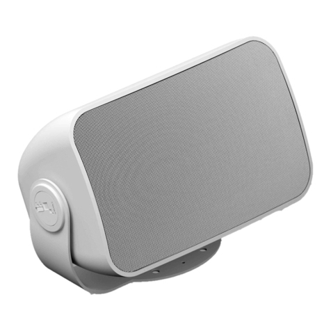
Grandstream Networks GSC3510 User manual

Grandstream Networks, Inc.
GSC3510/GSC3505 Series
User Manual

GSC3510/GSC3505 Series - User Manual
WELCOME
Thank you for purchasing Grandstream GSC3510/GSC3505 SIP Intercom speakers. The GSC3505 is a one-way SIP Intercom Speaker and GSC3510 is a
two-way full-duplex SIP intercom speaker/microphone, both featuring one 100Mbps Ethernet port with PoE/PoE+, integrated dual-band 2.4G/5G Wi-Fi,
integrated Bluetooth, high fidelity 8W speaker and a multi-purpose input port supporting a wide range of peripherals, 3 directional microphones with
Multichannel Microphone Array Design (MMAD) available for GSC3510 only. Both GSC3505 and GSC3510 with their Hi-Fi speaker delivers full-band
audio, while GSC3510 adds a state-of-art microphone array with pickup distance up to 4.2 meters. The built-in whitelist and blacklist features enable easy
filtering of unwanted calls from the Internet. Its modern industrial design and rich features make it ideal for classrooms, hospitals, apartments,
dormitories and much more.
PRODUCT OVERVIEW
Feature Highlights
The following table contains the major features of the GSC3510/GSC3505:
GSC3510
GSC3505
Up to 16 SIP accounts.
Ethernet RJ45 10/100Mbps, PoE/PoE+, Integrated Bluetooth, Wi-Fi.
Both GSC3505 and GSC3510 HD with their Hi-Fi speaker delivers full-band audio, Hands-free speakerphone with HD
acoustic chamber, advanced acoustic echo cancellation, while GSC3510 adds a state-of-art microphone array with pickup
distance up to 4.2 meters.
Table 1: GSC3510/GSC3505 Features in a Glance
GSC3510/GSC3505 Technical Specifications
The following table resumes all the technical specifications including the protocols / standards supported, voice codecs, telephony features, languages
and upgrade/provisioning settings for GSC3510/GSC3505.
Protocols/Standar
ds
SIP RFC3261, TCP/IP/UDP, RTP/RTCP, HTTP/HTTPS, ARP, ICMP, DNS (A record, SRV, NAPTR), DHCP, PPPoE, SSH, TFTP, NTP,
STUN, SIMPLE, LLDP-MED, LDAP, TR-069, 802.1x, TLS, SRTP, IPv6, OpenVPN .
Network
Interfaces Ethernet RJ45 10/100Mbps ports with integrated PoE/PoE+.
Bluetooth Yes, integrated. Bluetooth.
Wi-Fi Yes, dual-band 2.4 & 5GHz with 802.11 a/b/g/n.
Alarm Input 1 Alarm Input Port.
Voice Codec G.711µ/a, G.722 (wide-band), G.722.1, G.722.1C, G.726-32, iLBC, Opus, G.729A/B in-band and out-of-band DTMF (In audio,
RFC2833, SIP INFO).
Telephony
Features
Hold, transfer, forward (unconditional/no-answer/busy), call park/pickup, downloadable contacts, call record, call log, auto
answer, click-to-dial, flexible dial plan.
®

HD Audio Yes, HD speakerphone with support for wideband audio.
QoS Layer 2 QoS (802.1Q, 802.1p) and Layer 3 (ToS, DiffServ, MPLS) QoS.
Security User and administrator level passwords, MD5 and MD5-sess based authentication, 256-bit AES encrypted configuration file, TLS,
SRTP, HTTPS, 802.1x media access control.
Multi-languages English, Chinese and Portuguese.
Upgrade/
Provisioning
Firmware upgrade via TFTP / HTTP / HTTPS or local HTTP upload, mass provisioning using TR-069 or AES encrypted XML
configuration file.
Power and Green
Energy Efficiency Integrated PoE* 802.3af Class 3, PoE+ 802.3at, Class 4.
Package Content GSC3510/GSC3505, Metal Bracket, Plastic Bracket, Wiring Seat, Hang rope plate, 3x Screw (PM 3 x 50), 3x Screw (PA 3.5 x 20), 1 x
Screw (M3 x 15), Hexagonal Screwdriver, 3 x Plastic Expansion Bolt, 3 x M3 NUT, Quick Installation Guide, GPL license.
Physical Unit Dimensions: 215.32mm (diameter) x 68.7mm (depth)Unit Weight: 0.8kg, Box Weight: 1.39k
Compliance
FCC: Part 15 (CFR 47) Class B; UL 60950 (power adapter); FCC Part 15C, FCC Part 15E, MPE
CE: EN 55032; EN 55024; EN 61000-3-2; EN 61000-3-3; EN 60950-1; EN 301 489-1/17; EN 300 328; EN 301 893; EN 62311; RoHS
RCM: AS/NZS CISPR 32/24; AS/NZS 60950.1; AS/NZS 4268
IC: ICES 003, RSS 247, RSP-100, RSS 102
Table 2: GSC3510/GSC3505 Technical Specifications
GETTING STARTED
This chapter provides basic installation instructions including the list of the packaging contents and also information for obtaining the best performance
with the GSC3510/GSC3505.
Equipment Packaging
GSC3510/GSC3505
1x GSC3510/GSC3505 Main Case.
1x Metal Bracket.
1x Plastic Bracket.
Wiring Seat.
Hang rope plate.
3x Screw (PM 3×50)
3x Screw (PA 3.5 x20).
1x Screw (M3x15)
Hexagonal Screwdriver.
3x Plastic Expansion Bolt.
3x M3 NUT.
1x Quick Installation Guide.
1x GPL license.

Table 3: Equipment Packaging
Figure 1: GSC3510/GSC3505 Package Content
GSC3510/GSC3505 Ports
GSC3510/GSC3505 Ports
Figure 2: GSC3510/GSC3505 Ports
NO.
1
Name Description
RESET Factory reset button. Press for 10 seconds to reset factory default settings.
3
2
NET/PoE Ethernet RJ45 port (10/100Mbps) supporting PoE/PoE+.
2-PIN Port 2-PIN Multi-Purpose Input Port.
Table 4: GSC3510/GSC3505 Ports Description
GSC3510/GSC3505 LED Indicators
The GSC3510/GSC3505 contains 4 types of colored LEDs (Red, Green, White and Blue light) that are used in some specific situations and operations.
Please, refer to the following table describing each one of the LED Indicators status:
Note
Check the package before installation. If you find anything missing, contact your system administrator.

Color LED Indicator Status Description
Red Light FastFlashing (every1s) Rebooting/factoryre
setting
SlowFlashing
(On1s,Off2s)
Unhandledevent:(IncludedMissedcall(s),newvoice mails,newSIPmessages).
Note: In case the GSC3510/3505 is connected via Bluetooth, Missed Call/Voicemail Red LED will not
light and will remain flashing in blue.
SolidRed Thecontacts/storagespaceisfull
Green Light FastFlashing (every1s) Incoming/outgoingc
all
SlowFlashing
(On1s,Off2s) Callonhold.
SolidGreen During the call.
WhiteLight FastFlashing (every1s) Upgrading the
firmware.
BlueLight FastFlashing (every1s) Bluetoothpairing.
Table 5: GSC3510 LED Indicators
Hardware Installation
GSC3510/GSC3505 can be mounted on the wall or ceiling. Please refer to the following steps for the appropriate installation
Wall Mount
1. Locate the equipment holder on the desired position with arrow up. Drill three holes on the wall referring to the positions of holes on the metal
bracket.
2. Fix the metal bracket on the wall by expansion screws.
3. Align the position line on device’s back cover with the positioning slot.
4. Rotate the device clockwise until it is locked on the right position.
Figure 3: Wall Mount – Step 1
Figure 4: Wall Mount – Step 2

Figure 5: Wall Mount – Step 3 Figure 6: Wall Mount – Step 4
Ceiling Mount
1. Put the ceiling mounting (metal bracket) in the ceiling’s center and mark the position of the three screws holes.
2. Drill a round hole with a diameter of 18mm for Ethernet cable. The distance between its center and the highlighted hole on the plastic bracket
should be 35mm.
3. Fix the plastic and metal brackets on the ceiling with flat-head screws and locknuts. Then place and Ethernet cable pass through the 18mm-round
hole.
4. Align the position line on device’s back cover with the positioning slot.–––
5. Rotate the device clockwise until it is locked on the right position.
Figure 7: Ceiling Mount – Step 1 & 2 Figure 8: Ceiling Mount – Step 3
Figure 9: Ceiling Mount – Step 4 Figure 10: Ceiling Mount – Step 5
Anti-theft Installation
After the device is assembled with the metal bracket support on the wall or ceiling, use the anti-detachable screw (M3x15) in order to prevent theft.

Figure 11: Anti-theft Installation
Powering and Connecting GSC3510/GSC3505
The GSC3510/GSC3505 can be powered on using PoE/PoE+ switch or PoE injector using following steps:
Step 1: Plug a RJ45 Ethernet cable into the network port of the GSC3510/GSC3505.
Step 2: Plug the other end into the power over Ethernet (PoE) switch or PoE injector.
Figure 12: Powering GSC3505/GSC3510
Connecting Wiring Seat
GSC3505/GSC3510 support to connect a “Key & LED” or “Normal Key” to the 2-pin port via Wiring Seat using following steps:
Step 1: Take the wiring seat from the install kits.
Step 2: Connect the “Key & LED” or “Normal Key” with the wiring seat (as shown in the figure below)
Note
This port supports the parallel connection of an incandescent lamp (with less than 1W) or an LED lamp (with less than 100mA).

Figure 13: Connecting Wiring Seat
Access GSC3510/GSC3505 Web GUI
The GSC3510/GSC3505 embedded Web server responds to HTTP/HTTPS GET/POST requests. Embedded HTML pages allow users to configure the
application phone through a Web browser such as Microsoft’s IE, Mozilla Firefox, Google Chrome and etc.
Figure 14: GSC3510 Web GUI – Login
Users can use a computer connected to the same network as the GSC3510/GSC3505 to discover and access the GSC3510/GSC3505 Configuration
Interface using its MAC Address.
Please, refer to the following steps in order to access the GSC3510/GSC3505 Web GUI:
1. Locate the MAC address on the MAC tag of the unit, which is on the underside of the device, or on the package.
2. From a computer connected to same network as the GSC3510/GSC3505, type in the fol lowing address using the GSC3510/GSC3505’s MAC address
on your browser: https://gsc_<mac>.local
Example: if a GSC3510/GSC3505 has the MAC address C0:74:AD:xx:xx:xx, this unit can be accessed by typing https://gsc_c074adxxxxxx.local on the
browser.
GSC3510/GSC3505 APPLICATION SCENARIOS
GSC3510/GSC3505 SIP Two-Way/One-Way Intercom System
GSC3510/GSC3505 can be used as an Intercom System using built-in SIP accounts, once the SIP account registered the device can receive
paging/intercom calls and it will automatically answer calls coming from whitelisted numbers.
Note: GSC3505 is SIP one-way Intercom, while GSC3510 is two-way Intercom.

Figure 15: SIP 2-Way/1-Way Paging Diagram
To register a SIP account on the GSC3510/GSC3505 the user needs to go under Account 🡪 Account X 🡪 General Settings, and enter the account
information as below, then save and apply the configuration.
Figure 16: SIP Account Configuration
Once the account registered correctly, the GSC3510/GSC3505 will show the account status as “Registered” under Status 🡪 Account Status.
Figure 17: SIP Account Status
By default, the GSC3510/GSC3505 Blocks non-whitelisted number under Calls 🡪 Black/White List Settings 🡪 Blocking Rules, user needs to either
allow Non-White list calls or to set up a Whitelist that contains the number that will be allowed to call the GSC3510/GSC3505.

Figure 18: Default Blocking Rules
On the screenshot below, only number 1001 is allowed to call GSC3510/GSC3505:
Figure 19: Whitelisted Devices
As soon as a SIP call is received by the GSC3510/GSC3505, it first checks if the Caller ID number is allowed on the Whitelist and then answers
automatically.
Multicast Paging Application
Multicast paging is an approach to let different SIP users to listen for paging calls from a common multicast IP address. In multicast page call, an audio
connection will be set up from sender to receiver, but the receiver will be only able to receive audio, a one-way communication. The 2 entities,
Sender/Receiver, must be located on same LAN (same broadcast domain).
Figure 20: Multicast paging Diagram
To receive multicast page, GSC3510/GSC3505 must be well configured to listen to the right address and port. The configuration is located under Phone
Settings 🡪 Multicast Paging. Up to 10 listening addresses are supported with priority levels from 1 to 10.
Note: Multicast paging configuration requires a reboot to take effect.
Notes
GSC3510/GSC3505 is an intercom system and auto-answers all whitelisted numbers.
By default, GSC3510/GSC3505 plays a Warning tone when auto answering incoming calls, this warning tone can be disabled under Account 🡪 Account X
🡪 Call Settings, “Play Warning Tone for Auto Answer Intercom”.
Other manuals for GSC3510
1
This manual suits for next models
1
Table of contents
Other Grandstream Networks Speakers manuals

Grandstream Networks
Grandstream Networks GSC3516 User manual

Grandstream Networks
Grandstream Networks GSC35 Series User manual

Grandstream Networks
Grandstream Networks GSC3516 User manual

Grandstream Networks
Grandstream Networks GSC3516 User manual

Grandstream Networks
Grandstream Networks GSC3506 User manual