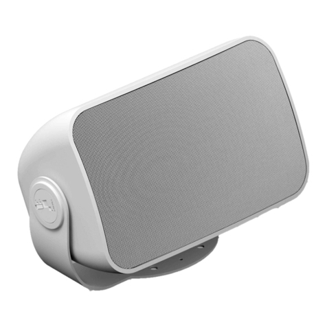
Genelec 4420A User manual

4420A
Operating Manual

1
GENERAL DESCRIPTION
The bi-amplified Smart IP Genelec 4420A install loudspeaker is a compact two-
way active loudspeaker for fixed installations. It requires only one CAT cable to
connect, making installation easy. The 4420A loudspeaker is powered using the
standard Power-over-Ethernet (PoE) technology, using PoE+ or PoE standards.
The proprietary internal power supply in 4420A delivers an impressive short-term
SPL.
The 4420 is a high-resolution loudspeaker delivering a signal path and acoustic
output that extends to ultrasonic frequencies. It uses Genelec’s Minimum
Diffraction Enclosure (MDE) enclosure technology to reduce acoustic diffractions.
Combined with the advanced Directivity Control Waveguide (DCW) surrounding
the tweeter, this provides excellent frequency balance in difficult acoustic
environments.
The 4420A loudspeaker supports Genelec Smart IP technology. The Smart IP
technology provides scalable power, audio and loudspeaker configuration,
supervision and calibration features via a standard CAT cable, offering
integrators unrivalled power, flexibility, cost-effectiveness and simplicity of
installation.
The 4420A has been designed for excellent sound quality and very long lifetime.
The enclosure is made of environmentally friendly recycled die-cast aluminium.
4420A is manufactured using certified sustainable methods. All essential parts of
the loudspeaker can be recycled.
The 4420A is available in black, white or 120 RAL colours on order. It is
compatible with Genelec’s extensive range of mounting accessories for floor,
ceiling, wall, or truss mounting.
The 4420A loudspeaker contains
• highly efficient dedicated Class D power amplifiers, one for each driver,
• switched-mode power supply technology offering high SPL output using
standard PoE+ and PoE power supply with an IP switch or power injector,
• active crossover filter,
• electronic system protection,
• audio-over-IP streaming input,
• balanced analogue line input,
• flexible room acoustic compensation tool set built in.

2
Audio-over-IP streaming supports unlimited number of channels in the playback
system. These audio channels are automatically synchronized perfectly in time
by the audio-over-IP streaming technology, forming a single playback system.
4420A accepts AES67/ST2110 and Dante audio-over-IP streams. The streams
are set up with Dante Controller or Dante Domain Manager software. Each
4420A supports reproduction of one or the sum of two audio input channels. The
stream audio sample rate can range 32-96 kHz, with 16-24 bit resolution.
The 4420A contains one rear panel CAT connector for standard Ethernet IP
network connectivity. The network interface speed is 100 Mbps. The rear panel
CAT connector also allows Genelec’s Smart IP Manager software to work on the
4420A. This software is available for AV installers at Genelec web site and runs
on Windows 10 computers. The software allows AV installers to configure an
almost unlimited number of rooms, zones, loudspeakers and audio channels, and
includes device discovery, a versatile room acoustic equalisation tool set, system
organisation and status monitoring.
The 4420A contains an application programming interface (API) supporting
control via third-party hardware, software or house automation. The API enables
integration to all house and home automation systems. Detailed information
about the API are provided in a separate document from Genelec.
A balanced line input is available on 4420A besides the CAT connector. The
balanced line analogue audio input in each loudspeaker can be configured to use
with Genelec Smart IP Manager software. When the balanced line input is used
the loudspeaker must still receive PoE power on the CAT cable.
The 4420A is designed for indoor use, in temperatures 15-35 Celsius and relative
humidity 20-90 %.
PACKING CONTENT
• Genelec two-way active loudspeaker 4420A.
• Keyhole-type wall mount with screws.
• Three-pin Euroblock connector for balanced analogue line input (inserted
in the loudspeaker).

3
Figure 1. Packing content, from left to right, loudspeaker, wall mount and
analogue input connector (inserted in the speaker).
POSITIONING AND MOUNTING THE LOUDSPEAKER
Place the loudspeaker so that the line of the acoustic axis points towards the
main listening area. The AV install designers may indicate different aiming.
Minimum clearance for amplifier cooling and reflex port function around the
loudspeaker is 3 cm (13/16 in) behind, above and on both sides of the
loudspeaker. If the back side of the loudspeaker is blocked, the back side of the
loudspeaker must be ventilated so that the ambient temperature remains below
35 C (95 F) under any moment of operation.
Figure 2. Definition of the acoustic axis.
The two primary mounting points are on the rear side. Use these for mounting
brackets or the keyhole wall mount adapter. They have metric M6 x 10 mm holes
(thread type is metric M6, thread depth is 10 mm). Do not exceed the thread
depth as this can result in failure of the thread. The base of the loudspeaker
carries a 3/8 in UNC-threaded hole compatible with a certain standard
microphone stands. This can be used for additional support. The UNC thread is
not compatible with metric threads. Do not use this point as the primary mounting
point. Pay attention to mounting screw lengths. Do not use screws exceeding the
depth of the hole as this can destroy the threads in the mounting points. Do not
over-tighten. Do not use very short screws as the thread length covered by such
screw is not enough to hold the weight of the speaker.

4
See Genelec Accessories Catalogue on www.genelec.com for a complete list of
mounting hardware options. The accessories can come with instructions on the
proper methods of installation.
Figure 3. Connectors and controls in the 4420A rear panel.
CONNECTING LOUDSPEAKERS
To get started, connect an Ethernet cable from the PoE+ output in an IP switch to
the 4420A Ethernet port. Use at least CAT5 cable or better. Press the power
switch to power up the loudspeaker.
To create a working system, you will need
• IP switch with a PoE+ (802.3at) output for the 4420A loudspeaker
or an IP switch with no PoE support and a PoE+ power injector
• CAT 5 or higher category Ethernet cable with RJ45 connectors
• AES67, ST2110 or Dante audio-over-IP stream source
• For 4420A setup and configuration, a computer running Macintosh OS X
or Windows 10 operating system
• Genelec Smart IP Manager software
• Dante Controller software or Dante Domain Manager software
THREADS FOR
WALL MOUNT
BRACKET
POWER
SWITCH
BALANCED
ANALOGUE
INPUT
ETHERNET
PORT

5
Figure 4. 4420A powered with PoE+ IP switch.
Example of powering the 4420A with a PoE+ enabled IP switch. With this
method, the power budget available for all outputs connected to the IP switch
must enable each 4420A to run at full PoE+ power. For 4 loudspeakers, the
power supply must support 4 x PoE+ power level.
Figure 5. 4420A powered by an IP PoE+ power injector.
Example of powering the 4420A with a PoE+ power injector. This method
enables the use of standard non-PoE IP switches. Each power injector must
support full PoE+ power level into the device.

6
How PoE power management works
The 4420A internal power supply stores power for peak output. This enables the
output power to exceed the input power for short durations (Figure 6). Music and
speck signals are dynamic. They contain high peaks above the average level.
These peaks are supplied from the energy stored in the loudspeaker power
supply. The power supply has been dimensioned to work with audio and speech
signals, including highly compressed wideband audio signals. The duration of
peak output is limited more by the PoE supply and therefore Genelec
recommends the use of PoE+ supply whenever possible.
Figure 6. 4420A power supply enables high output level peaks exceeding the
incoming PoE power level; the PoE standard limits the duration of the peaks
PoE budget calculation
The 4420A supports automatic negotiation with the IP switch or IP power injector
to set the PoE power level. However, in some cases it may be necessary to set
the PoE power level in the switch manually.
Table 1. PoE and PoE+ power levels.
Name
Standard
Power at switch
Min. power at 4420A
PoE
IEEE 802.3af-2003
15.4 W
12.95 W
PoE+
IEEE 802.3at-2009
30 W
25.5 W
There are several Power-over-Ethernet standards. The 4420A loudspeaker
supports the PoE+ standard but also works with the lower power PoE standard.
When the 4420A also works with lower PoE power, the duration of high SPL
output is shortened, and long continuous output signals play at smaller sound
level than when the PoE+ power level is used. Genelec recommends using PoE+
power level with 4420A.

7
Each PoE supply device (IP switch or power injector) has a certain maximum
output power capacity. This can limit the number of PoE outputs that can be set
on. For 4420A loudspeaker, calculate the output power for each output as 15.4
W for PoE and 30 W for PoE+. Ensure that the total power does not exceed the
switch or power injector total power.
Example: IP switch total power is 150 W. You use PoE+ and four outputs are
connected. The total output power is 4 x 30 W = 120 W. This is smaller than the
capacity of the Ip switch, 150 W. This scenario is acceptable.
PoE cable loss calculation
There is power loss in the Ethernet cable. The reason for the power loss is that
the CAT cable conductor is thin and has considerable resistance. The power loss
increases with increasing cable length. The maximum cable length is 100 meters
(333 feet). Calculate the power loss in cable at 25 mW/m or 7,4 mW/ft. 4420A will
automatically adapt to the power loss in the cable, but lower input power will
affect slightly the duration of the maximum SPL output. In order to minimize the
cable loss and to maximize the duration at maximum SPL, consider using power
injectors close to the loudspeakers or short cable runs.
ISS AUTOSTART
The automatic power function ISS (Intelligent Signal Sensing) powers the
loudspeaker automatically down when it is not in used and up when the use
resumes. ISS can be activated and adjusted with the Smart IP Manager
software. Powering down to standby happens after a set time when playback has
ended. Playback automatically resumes with an input signal exceeding the level
configured using the Smart IP Manager. There is a slight delay in the automatic
powering up. If this is undesirable, ISS can be disabled with Smart IP Manager.
The indented use of this loudspeaker requires that the IP network interface is
continuously enabled also in the standby mode. This enables the ISS to wake up
with an API command or in response to IP audio stream. The power consumption
in the ISS state for 4420A is 4 W. To save more power, the PoE+ power supply
in the Ethernet switch or PoE injector can be turned off. However, loudspeaker
wakeup will then take slightly longer time and the loudspeaker does not respond
to any command on the IP network while it is not powered.
SELECTION OF IP SWITCH
Smart IP and 4420A are fully compatible with standard Ethernet and IP switch
technology. Genelec recommends using gigabit speed managed IP switches with
full PoE+ on each of the outputs intended for 4420A loudspeakers. Managed IP
switches offer the ability to configure, manage and monitor the local area

8
network, typically using a web browser user interface, and this helps in creating a
well working system.
The IP switches should support QoS and be media ready. Differentiated services
(DiffServ) typically implements QoS prioritization of IP traffic. DiffServ marks IP
packets according priority. In response, IP switches can prioritize media traffic to
improve system performance. Differentiated services code point (DSCP)
markings in the IP packet headers are sensed by the QoS capable IP switch.
Genelec does not endorse certain IP switch brands as Smart IP works perfectly
with all high-quality standard IP switches with these capabilities. Use of 100
Mbps IP switches is discouraged.
NETWORK STRUCTURE
Genelec recommends always designing a network structure with star topology.
Only one IP device (for example, one 4420A) should be connected at one port in
an IP switch. IP device ports should not be daisy chained to several IP devices.
Audio-over-IP requires the use of cable-based LAN network. Low-latency
uncompressed audio-over-IP streaming does not work over WLAN.
SETTING UP AUDIO STREAMS
Audio stream setup is done by using Dante Controller software. Download the
software from https://www.audinate.com/products/software/dante-controller
An AES67/ST2110 audio stream supported by the loudspeaker can have contain
the maximum of 8 audio channels. Dante automatically divides a multichannel
stream into several low channel count flows suitable for the speaker and this
process is largely automatic.
The 4420A can select one audio channel or a sum of two channels in a stream.
The AES67 compatibility mode must turned ON to enable reception of AES67 or
ST2110 streams. Follow these instructions:
• Double click on the loudspeaker to be configured. The Device View
window opens.
• Click AES67 Config -tab.
• In the AES67 Mode panel, go to New: and select Enabled.
• In the Reset Device panel, click Reboot to reboot loudspeaker with
AES67 enabled.

9
Figure 7. Configuring for AES67/ST2110 streams in the Dante controller.
ANALOG INPUT
An analogue audio input is provided using a screw-mount Euroblock connector.
This enables easy connectivity and daisy-chaining the balanced audio signal to
several loudspeakers. When you daisy-chain loudspeakers, connect a second
signal cable to the plug (Figure 8).
The input impedance of the analogue input is 10 kOhm. The pin sequence of the
connector is shown in Figure 8. The number of loudspeakers that can be on the
same daisy chain is set by the capability of the source device analogue output.
The daisy-chained loudspeakers appear electrically in parallel, reducing the load
impedance presented to the source device. Typically, 10 to 20 loudspeakers can
be daisy-chained on one balanced line.
Avoid connecting 4420A to the power amplifier outputs. If this must be done, use
a balanced attenuator. Typically, an attenuation of about 20 dB is needed.
Beware that some power amplifiers can provide a signal that exceeds the
maximum voltage at the analogue input, and this can result in failure of the
analogue input.
Other manuals for 4420A
2
Table of contents
Other Genelec Speakers manuals

Genelec
Genelec PowerPak 8030A User manual

Genelec
Genelec 1030A User manual

Genelec
Genelec S30 Series User manual

Genelec
Genelec 6010A User manual

Genelec
Genelec 1039A User manual

Genelec
Genelec 8030 User manual

Genelec
Genelec S30DH User guide

Genelec
Genelec 4010A User manual

Genelec
Genelec 8040B User manual

Genelec
Genelec AIC25 User manual

Genelec
Genelec 8020D User manual

Genelec
Genelec AOW312 User manual

Genelec
Genelec 4040A User manual

Genelec
Genelec 1038A User manual

Genelec
Genelec 1032A User manual

Genelec
Genelec 4010A User manual

Genelec
Genelec M040 User manual

Genelec
Genelec 1039A User manual

Genelec
Genelec 1022B User manual

Genelec
Genelec 8020B User manual