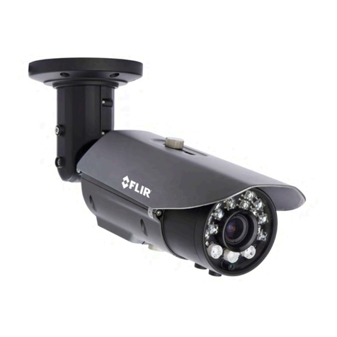
FLIR Quasar CB-6404 User manual

CB-6404/CB-6408 QIG Rev 100
February 2021
This document does not contain any export-controlled information.
Quasar™ Bullet
CB-6404/CB-6408
Quick Install Guide
1 Check Contents
Make sure all of the items above are included in the camera kit.
2 Select a Location
Select a suitable location to mount the camera. Make sure that when mounted, the
camera’s general orientation covers the required field of view.
For advice on positioning and orienting the camera, see the camera's installation
and user guide.
Verify that the operating temperature range is between -40°C ~ 60°C (-40° ~ 140°
F) cold start, 0-95% relative humidity.
For the list of mounting accessories available for the camera, see the FLIR
Security Cameras - Accessory Guide.
3 Configure the Camera
FLIR recommends configuring the camera before mounting and aiming it. It is also
possible to configure the camera after mounting it, which could be more
appropriate for certain installations.

CB-6404/CB-6408 QIG Rev 100
February 2021
This document does not contain any export-controlled information.
3.1 Install the FLIR DNA tool
The FLIR Discovery Network Assistant (DNA) tool does not require a license to
use and it is free. Download it from the FLIR Quasar™ Premium Bullet pages at
FLIR.com > Products > Security > Visible Security Cameras. Save the ZIP file on a
computer running Windows on the same VLAN to which you will connect the
camera. Then, unzip the file.
3.2 Connect the Camera
System Cable
a. Attach an Ethernet cable from the
network switch to the RJ45 connector for
a 10/100/1000 Mbps Ethernet and PoE+
(Power over Ethernet) IEEE 802.3at
connection. Ethernet is required for
streaming video and for configuring the
camera.
b. Connect the audio and alarm connectors,
if needed.
c. If using an external DC or AC power
supply, connect its wires to the two-pin
terminal block. Then, attach the terminal
block to the system cable's two-pin power
connector.
Connector
1
Black
RJ-45
2
Black
12 VDC/24 VAC -
Red
12 VDC/24 VAC+
3
Yellow
AUDIO IN+
Orange
AUDIO IN-
Purple
AUDIO OUT+
Green
AUDIO OUT-
Red
ALARM IN Signal
Black
ALARM IN GND
Brown
ALARM OUT Signal
Blue
ALARM OUT COM
e. (Optional) Insert a microSD card into the slot on the camera body. For
information about accessing the microSD card slot and the camera's other
internal interfaces, see the camera's installation and user guide.
3.3 Configure for Networking
You can configure the camera using version 2.3.0.20 or higher of the DNA tool,
the camera's web page, or a supported VMS.
Task
DNA tool
Camera's web page
Discover camera IP address
•
Configure IP address, mask, and gateway
•
•
Configure DNS settings, MTU, and Ethernet speed
•
Change user credentials
•
•

CB-6404/CB-6408 QIG Rev 100
February 2021
This document does not contain any export-controlled information.
Task
DNA tool
Camera's web page
Change video format
•
•
Configure more than one camera at the same time
•
For information about using the camera's web page to configure the camera, see
the camera's installation and user guide. For information about using a supported
VMS to configure the camera, see the VMS documentation.
By default, DHCP is enabled on the camera and a DHCP server on the network
assigns the camera an IP address. For example, if the camera is managed by
FLIR's Horizon or Meridian VMS and the VMS is configured as a DHCP server, the
VMS automatically assigns the camera an IP address.
If the camera is managed by FLIR’s Latitude VMS or is on a network with static IP
addressing, you can manually specify the camera’s IP address using the DNA tool
or the camera's web page. The camera's default IP address is 192.168.0.250.
To manually specify the camera's IP address using the DNA tool:
a. Make sure the camera and the PC are on the same LAN segment.
b. Run the DNA tool (DNA.exe) by double-clicking .
The Discover List
appears, showing
compatible
devices on the
LAN segment and
their current IP
addresses.
In the DNA Discover List, verify that the camera's status is Online.
If this is the first time you are configuring the camera or if it is the first time after
resetting the camera to its factory defaults, DNA automatically authenticates
the camera with the default password for the camera's admin user (admin).
If the admin user password has been changed, you need to authenticate the
camera.
In the DNA Discover List, right-click the camera and select Login.
In the DNA - Login window, type the password for the admin user. If you do
not know the admin user password, contact the person who configured the
camera's users and passwords.
Click Login, wait for Ok status to appear, and then click Close.

CB-6404/CB-6408 QIG Rev 100
February 2021
This document does not contain any export-controlled information.
In the DNA Discover List, verify that the camera's status is Authenticated.
c. Change the camera’s IP address.
Right-click the camera and select IP Setup.
In the DNA - IP Setup window, clear Use
DHCP and specify the camera's IP
address. You can also specify the Mask
(default: 255.255.255.0) and Gateway.
Then, click Update, wait for Ok status
to appear, and then click Close.
3.4 Change Video Format (Optional)
By default, NTSC is the camera's video format.
To change the camera's video format to
PAL using the DNA tool:
a. In the DNA Discover List, right-click the
camera and select Change Video Format.
b. In the Change Video Format window,
select PAL.
c. Click Update, wait for Ok status to
appear, and then click Close.
For more information about using the DNA tool to configure one or more cameras,
see the DNA User Guide. While the software is open, click the Help icon
.
4 Install the Camera
Warning
The camera must be installed by qualified personnel and the installation should
conform to all local codes.
Be sure to have the required accessories and tools available and refer to the
camera's installation and user guide as necessary.
4.1 Fit Mounting Hardware
If required, install additional mounting hardware for the camera according to the
instructions for the hardware.

CB-6404/CB-6408 QIG Rev 100
February 2021
This document does not contain any export-controlled information.
4.2 Mount Back Box and Route Cables
To maintain structural integrity, before drilling into the mounting surface, make
sure it is at least 50mm (2”) thick.
a. Using the mounting template, drill six holes on the wall or mounting surface:
Diameter 3/8” (9.5mm), depth 1/1/2” (40mm). To ensure proper installation,
make sure the drilled holes are of correct size.
b. Hammer the six screw anchors into the drilled holes.
c. Cables can enter the back box from the rear or from the side. If the cables are
going to enter from the rear, use the mounting template to drill a bottom conduit
hole for the cables.
d. Route the power and network cabling into the
back box.
·
If you are connecting the camera using a single
Ethernet cable with an RJ45 plug attached,
attach the RJ45 insertion tool included with the
camera to the RJ45 plug. Then, route the tool,
plug, and cable through the single cable rubber
seal included with the camera.
·
If you are connecting the camera in any other
way, route the cables through the multiple cable
rubber seal included with the camera.
Securely fasten the rubber seal to either the
bottom or the side conduit hole. In addition, FLIR
recommends applying 3M waterproofing tape on
the cables that pass through either conduit hole.
RJ45 Insertion
Tool
Single Cable
Rubber Seal
e. Mount the back box onto the wall or
surface. Using the Philips head
screwdriver, fasten the six TP4
tapping screws into the six screw
anchors.
Connect the Camera
Inside the back box, connect the
camera's system cable to the other
cables according to the information in 3.2
Connect the Camera.
Mount Back Box
4.3 Mount and Aim the Camera
a. Attach the camera to the back box. With the
camera attached to the adapter plate, align the
triangle on the adapter plate with the triangle on
the back box.
Then, while carefully holding and fully supporting
the camera, to make sure the screws are not
bearing the camera's weight when tightening
them, use the Torx wrench to tighten the three
T20 screws attached to the adapter plate.

CB-6404/CB-6408 QIG Rev 100
February 2021
This document does not contain any export-controlled information.
Attach Camera to Back Box
Mounting Complete
b. Adjust the sun shield.
Loosen the two screws on the shield
hood.
Move the sun shield forward or
backward.
Tighten the two screws.
c. Aim the camera.
While supporting the camera with
your hand, loosen the three locking
screws and adjust the camera's pan,
tilt, and rotation.
d. Make sure that the toothed surfaces
are properly aligned and meet
evenly. Then, use the T10 torx
wrench to securely tighten each
locking screw.

CB-6404/CB-6408 QIG Rev 100
February 2021
This document does not contain any export-controlled information.
5 Complete Camera Setup
Specify the camera's zoom and focus, and format the
microSDXC card, using the camera's web page, which
supports Google Chrome (recommended), Firefox,
Microsoft Edge, and Internet Explorer 11 (32-bit), on PCs
running 64-bit Windows 7, 8, 8.1, or 10.
a. Log in to the camera’s web page.
In the DNA Discover List, double-click the camera.
On the login screen, type a user name and password.
Both are case-sensitive.
When logging in to the camera's web page for the first time or for the first
time after resetting the camera to its factory defaults, type admin for the user
name and for the password.
Then, specify a new password for the admin user. Use a strong password
consisting of at least eight characters and at least one uppercase letter, one
lowercase letter, and one number. Passwords can include the following
special characters: |@#~!$&<>+_-.,*?= .
Log back in using the new password.
The camera's View Settings Home Page opens.
b. Using the controls under the live video, configure the camera's focus and
zoom.

CB-6404/CB-6408 QIG Rev 100
February 2021
This document does not contain any export-controlled information.
c. Format the microSDXC card.
Click System Settings.
In the top navigation bar, click SD
Card.
Under SD Format, click Format.
For more information about using the camera's web page to configure the camera,
see the camera's installation and user guide.
6 Attach the Camera to a Supported VMS
After mounting the camera and discovering or defining its IP address, use VMS
Discovery/Attach procedures to attach the camera to a supported VMS.
7 Camera Dimensions
The Quasar CB-6404/CB-6408 camera’s dimensions are:
Side View
Front View
8 Register the Product
Register your Product with FLIR at https://customer.flir.com.
For warranty information, see https://www.flir.com/support-
center/warranty/security/flir-security-product-warranties/.
9 Contact Information
FLIR Systems, Inc.
6769 Hollister Avenue
Goleta, CA 93117
USA
Support: https://www.flir.com/support/
product.enterprise.support@flir.com
Corporate Headquarters
27700 SW Parkway Ave.
Wilsonville, OR 97070
USA
This manual suits for next models
1
Table of contents
Other FLIR Security Camera manuals

FLIR
FLIR CP-6302-30-R User manual

FLIR
FLIR Quasar Gen III Manual

FLIR
FLIR QUASAR CP-3211 Manual

FLIR
FLIR C233BC User manual

FLIR
FLIR SV87-KIT User manual

FLIR
FLIR Navigator II User manual

FLIR
FLIR P143E4 SERIES User manual

FLIR
FLIR MPX ME313L User manual

FLIR
FLIR IP Series User manual

FLIR
FLIR C336ZC1 Operating and maintenance manual

FLIR
FLIR C23 Series User manual

FLIR
FLIR DNV14UX2R User manual

FLIR
FLIR Quasar CP-6408 User manual

FLIR
FLIR SyncroIP Camera Series User manual

FLIR
FLIR DCV64DL User manual

FLIR
FLIR FB-Series Assembly instructions

FLIR
FLIR PT series User manual

FLIR
FLIR Photon User manual

FLIR
FLIR Quasar CP-6408-21-I User manual

FLIR
FLIR FB-Series User manual