Fei Bao F-9F Panther User manual

F E I B A O F - 9 F P A N T H E R
1
11
1
FEI BAO JETS
F-9F Panther Assembly Manual
Written by Curtis Mattiko
In collaboration ith R/C Jet Models

F E I B A O F - 9 F P A N T H E R
2
22
2
DISCLAIMER:
THIS IS NOT A TOY. This is a high-performance miniature aircraft, capable of high
speeds and damage to life, limb, and property. The manufacturer and its distributors cannot
control how you assemble this model, what equipment you use to fit it out, or how you fly it,
and can assume no liability whatsoever for any damages that may occur when you fly your
aircraft. By assembling this model, you are agreeing to indemnify and hold blameless the
manufacturer and/or his agents from any and all torts and liability associated with the use of
this product. Please inspect all parts before beginning assembly. If any parts appear to be
suspect, contact your dealer or the manufacturer for repair or replacement B FOR you
begin. Once you have assembled the aircraft, you are the pilot in command and assume any
and all responsibility for the use of the model and any damages that might occur by flying or
attempting to fly this aircraft.
R/C model jets require a high level of skill in both their assembly and their flying. If you do
not feel confident in either your building or flying skills, PL AS seek assistance from more
experienced modelers. It is a wise idea, no matter what level of skills you possess, to have a
second experienced modeler go over your installation after assembly. A second set of eyes
may spot a problem you have missed. If you have not flown a model like this before, it is
HIGHLY recommended that you get an experienced turbine pilot to do your maiden flight.
Very often, the first few seconds of a maiden flight are critical until the aircraft is trimmed
out, and having an experienced pilot at the controls can make the difference between a
wrecked aircraft and once that enjoys many hundreds of flights. Be sure to select a suitable
field for flying...take the time to find a large paved runway if at all possible, especially for test
flights, until you feel comfortable getting the aircraft in and out of smaller grass fields.
BEFORE YOU BEGIN:
Keep this in mind as you proceed:
Look at V RY assembly step you finish, and ask yourself:
"Is this going to crash my airplane?"
A chain is only as strong as its weakest link, and this is a high-performance aircraft that will
be very intolerant of sloppy assembly techniques. ven the smallest component is important
and can cause the loss of your airplane, so take the time to do things right. Or R do them if
they are wrong. Careful work will result in a long-lasting plane that gives you years of
pleasure, one loose component could result in the complete loss of the aircraft and all the
components inside it, and someone can even get hurt. So pause every once in a while when
building it and double-check your workmanship.
F9F as it comes from the factory ith combo and factory Installation
option:
Accessories included:

F E I B A O F - 9 F P A N T H E R
3
33
3
Stainless steel double-walled tailpipe
Two wooden formers for tailpipe
Two wooden engines mount spacers for Jetcat engines
One whip antenna
Three coils of airline
One coil of fuel line
One brake valve
One retract valve
One bag of air y-connectors
One bag of fuel y-connectors
One bag of fuel plugs
One bag of air disconnects
7 linkages
2 air tanks
One bag of servo mounts with hardware
One bag of screws and bolts
One bag with steering cable and tubing for crimping
Aircraft parts included:
One forward fuselage with landing gear and doors installed
One rear fuselage section with lower rudder installed
Two wings with flaps and ailerons installed
One stab with elevator installed
One upper fin with rudder installed
Two tip tanks
One center hatch
One canopy assembly
One cockpit tub assembly

F E I B A O F - 9 F P A N T H E R
4
44
4
A. Introduction:
You have chosen a model that represents the pinnacle of ARF technology. While there is
not a lot of building to do, there is enough to keep you busy for a few evenings.
ven if you have assembled maybe other ARF jets, we highly recommend following our
assembly sequence and procedures anyway.
Chances are it will save you a lot of time, prevent you from running down dead ends, and
perhaps remind you of a few small things that might end up saving your aircraft.
We have tried to arrange a construction sequence that will allow you to keep moving
forward, rather than standing around waiting for glue to dry before you can proceed to the
next step.
Just because the model is almost completely built does not mean you can rush through the
final assembly.
You need to employ fine craftsmanship every step of the way, turbine models are critical.
Keep this in mind with everything you do, every part you install...look at the work you just
did, evaluate it critically, and ask yourself "is this going to potentially crash my airplane?" If
there is any doubt about the work you have done, back up, and re-do it properly.
B. Adhesives:
The correct adhesive to use for all procedures is Loctite Hysol 9462. This is a very strong
white epoxy that is thixotropic. "Thixotropic" means it does not run at all, but stays only
where you put it. It is infinitely superior to regular epoxy, even slow-setting epoxy, for our
purposes, because of this characteristic.
Regular epoxy will run downhill with gravity as it dries, taking it away from where it is
supposed to be.
A good example is in the hinges...using regular epoxy, a good portion of the glue will migrate
down away from the hinge into the inside of the wing as it dries, and you won't even know it
is happening. Hysol stays where you put it.
The downside of Hysol is it takes overnight to dry properly, but we have tried to arrange
things to keep you busy while waiting for glue to dry.
We also highly recommend that you only use a proper Hysol dispensing gun, and only the
long-type mixing nozzles.
The short nozzles do not mix this glue enough, and only a thin nozzle and gun will let you
fill the hinge and control horn holes properly with glue, you can't do it mixing your Hysol on
a flat surface and trying to get the glue in the proper place by a brush or stick.
You can buy a complete Hysol setup with a gun, nozzles, and two cartridges of glue from
your dealer for approximately $60.
Consider it a great investment, the glue is the best you will use. One cartridge is plenty to
assemble your F-9F.
F E I B A O F - 9 F P A N T H E R
5
55
5
C. WORKING WITH PNEUMATIC SYSTEMS:
The F-9F uses pneumatic brakes and retracts. If you follow a few tips, you should have very
reliable, leak-free operation. Neatness counts.
All airlines should be secured to the airframe to keep them from flopping around or getting
kinked. Use tie wraps for this.
The other very important thing is to cut off the end of each airline dead square before
installing it on the nipple.
This is VITAL. You can either purchase a professional tubing cutter from your dealer (they
are approximately $10), or you can make up a little jig to hold the airline and keep a sharp,
new razor blade perfectly upright as you cut.
ither one works, just ensure that all ends of all airlines are cut off dead square. Make sure
all airlines are pushed ALL TH WAY onto their nipples.
They should not need to be secured otherwise, but you can add fine wire safety wraps if you
like. Make sure all left and right matching airlines are the same length, particularly the brake
lines, or you will get uneven retraction or braking action.
It's worth taking the time to get everything pneumatic right the first time, as having your
landing gear fail to retract is not THAT bad, but having it fail to deploy can really ruin you
day and the paint on the bottom of your model.
D. FUEL SYSTEM:
The F-9F has a very simple fuel system...one main tank leading to a UAT or similar header
tank.
There is not much to go wrong, but like the pneumatic system, it does need to be done right
the first time, with some careful craftsmanship.
Like the airlines, all fuel lines must be cut off Dead Square. ach fuel connection should be
given a tie-wrap or two for extra security.
verything needs to be dead clean, especially the inside of the main tank.
The front tray is set up to accommodate a BVM Ultimate Air Trap or it's equivalent, to keep
any bubbles from getting to your engine.
You can also make up your own header tank with a bubbles filter, or a geometrically
centered pickup, but any way you do it, you should not attempt to fly without a header tank
system. Move on to the main fuel tank. Blow out the main fuel tank, be sure that no debris
of any sort is left in there before proceeding. This is a vital step, do not omit it.
F E I B A O F - 9 F P A N T H E R
6
66
6
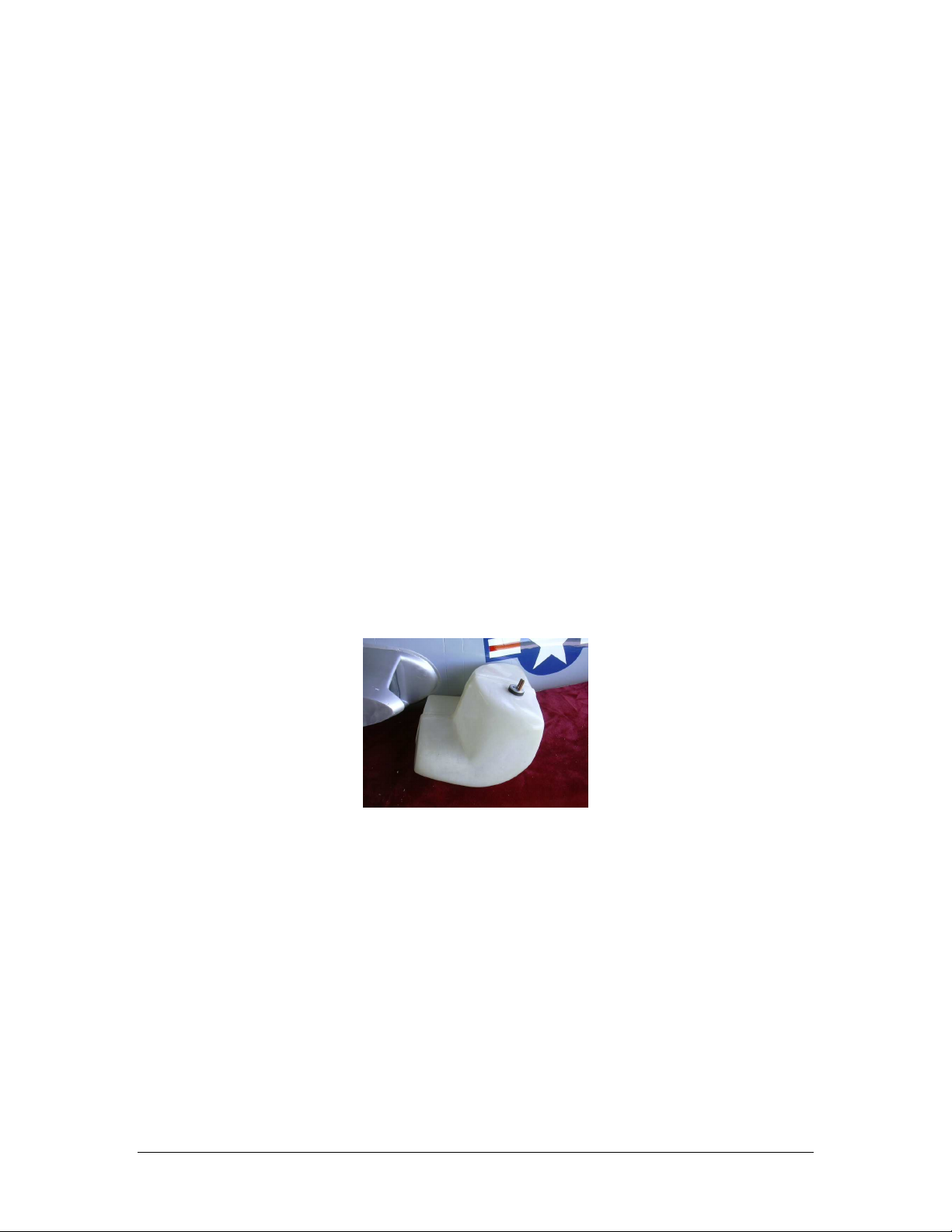
1. Remove the servo cover from the rudder servo bay. Keep the orientation of
the servo cover correct, do not flip or rotate the servo covers, as there may
be slight variations in the screw holes and they may not fit perfectly if you
rotate the covers.
Figure 1
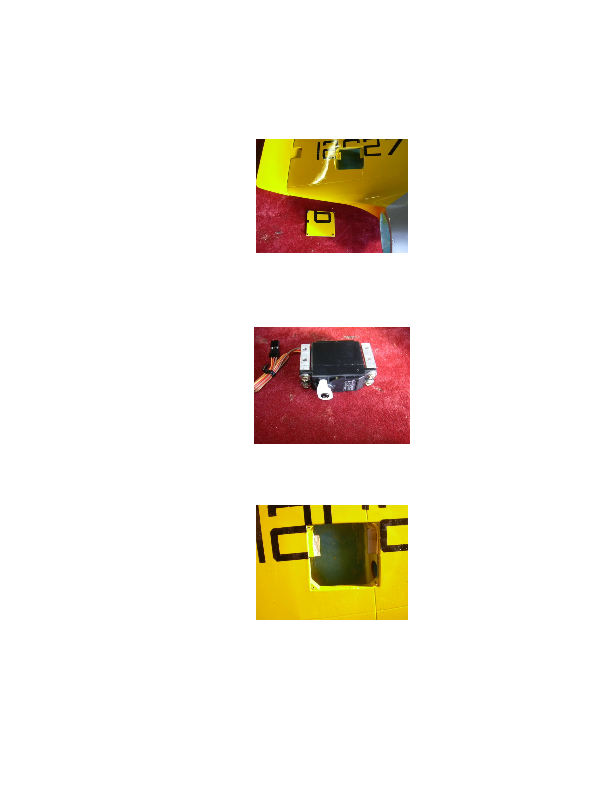
2. Fit the supplied aluminum mounts to the servo, using the supplied screws.
Do not over tighten and strip the screws. Do not use any grommets or other
servo hardware. Secure the screws with Locktite
Figure 2
3. Check the depth of the servo mount with the servo. Relieve if needed with a
sharp exacto knife.
Figure 3
F E I B A O F - 9 F P A N T H E R
7
77
7
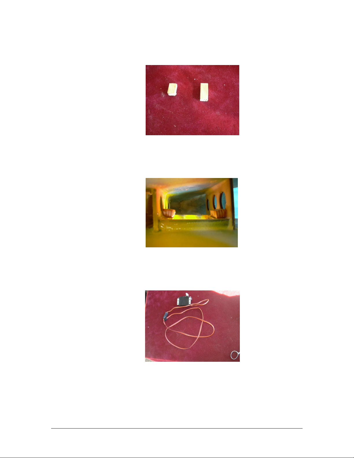
4. Make up some scrap hardwood or plywood blocks the same size as the servo
mounts.
Figure 4
5. poxy the scrap blocks on the inside of the mounts to provide extra
strength.
Figure 5
6. Attach a 36" heavy-duty 22 gauge extension to the servo. Tape the
connection for safety.
Figure 6
F E I B A O F - 9 F P A N T H E R
8
88
8
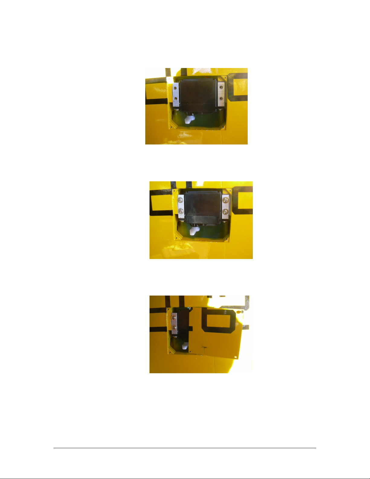
7. Dril pilot holes in the wooden mounts
Figure 7
8. Screw the servo with the kit provided screws. Do not over tighten and strip
the screw holes.
Figure 8
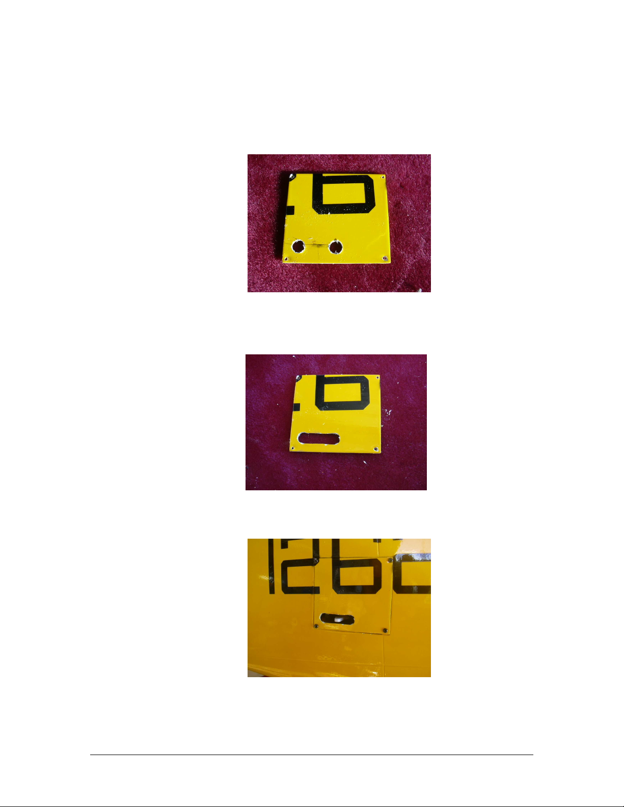
9. Fit the servo cover up against the model and mark the location for the servo
horn.
Figure 9
F E I B A O F - 9 F P A N T H E R
9
99
9
10. Drill a hole at each end of the slot. Be sure to put a piece of scrap plywood
on the back side before you drill, it will give you a clean hole without
marking up the finish that way.
Figure 10
11. Draw two lines between the holes with a straightedge and soft pencil. Cut at
the lines using an exacto with a new sharp blade.
Figure 11
12. Screw the servo cover into place.
Figure 12
F E I B A O F - 9 F P A N T H E R
10
1010
10
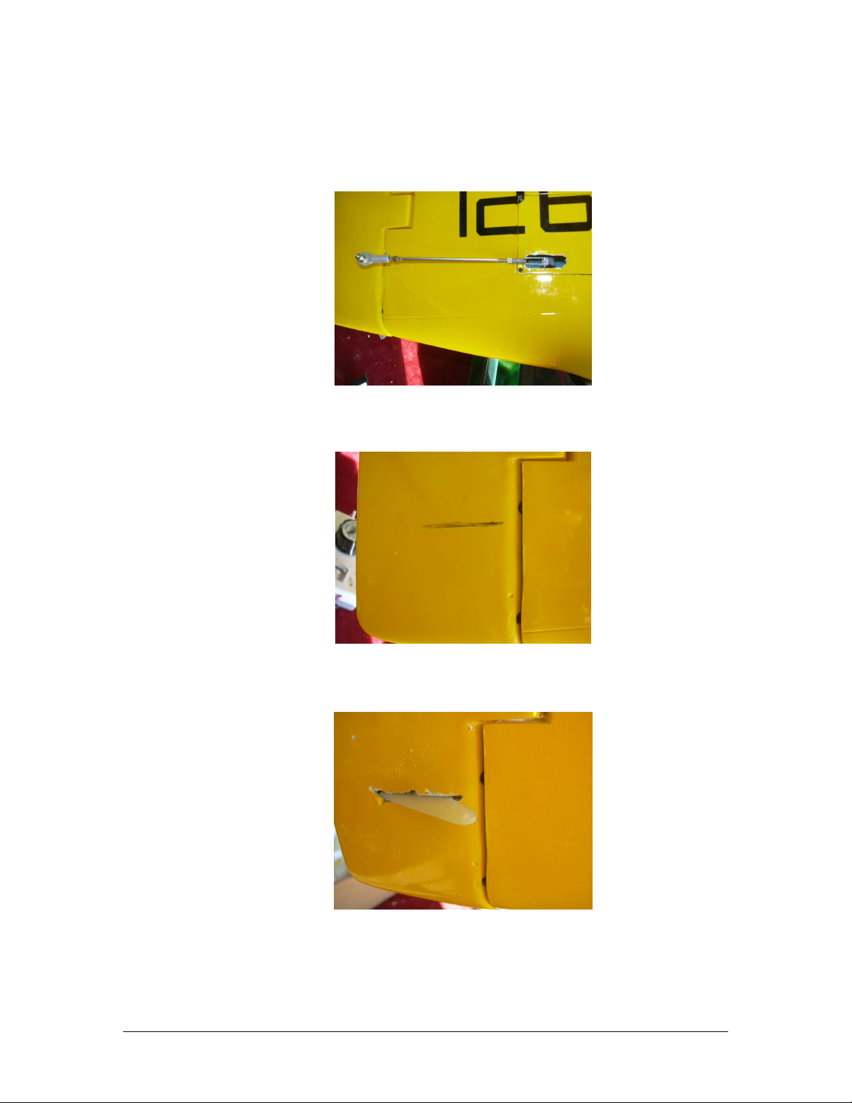
13. Fit the ruder pushrod to the servo horn
Figure 13
14. Using the rod for reference, mark the location of the rudder control horn.
Figure 14
15. Cut the slot for the control horn.
Figure 15
Table of contents
Other Fei Bao Toy manuals

Fei Bao
Fei Bao Mirage F1 User manual

Fei Bao
Fei Bao EF2000 User manual

Fei Bao
Fei Bao Mirage 2000 User manual

Fei Bao
Fei Bao SU-27 User manual

Fei Bao
Fei Bao L-39 User manual

Fei Bao
Fei Bao MiG-21 Fishbed User manual

Fei Bao
Fei Bao F18-f User manual

Fei Bao
Fei Bao F-4 Phantom II User manual

Fei Bao
Fei Bao MB-339 User manual

Fei Bao
Fei Bao T45 User manual


