Exhausto EXact2 VEX200 User manual

EXHAUSTO A/S
Odensevej 76
DK-5550 Langeskov
Tel. +45 65 66 12 34
Fax +45 65 66 11 10
www.exhausto.dk
3006324-2021-12-14.fm
VEX200
Automatic leakage
control EXact2
RU

3006324-2021-12-14.fm
2/44
1. UK - Product information
1.1 In general.............................................................................................................. 4
1.2 Application ........................................................................................................... 4
1.3 Conditions ............................................................................................................ 4
1.4 Proviso:.................................................................................................................4
1.5 Operating Mode.................................................................................................... 4
1.6 Operating conditions........................................................................................... 5
2. Connection
2.1 Cable connection................................................................................................. 6
2.2 VEX240-250-260-270-280 Fan placement with ALC .......................................... 7
2.2.1 Fan placement VP1R ................................................................................... 7
2.2.2 Fan placement VP1L .................................................................................... 7
2.2.3 Fan placement VP2R ................................................................................... 8
2.2.4 Fan placement VP2L .................................................................................... 8
1. DK - Produkt information
1.1 Generelt ................................................................................................................ 9
1.2 Anvendelse........................................................................................................... 9
1.3 Forudsætninger ................................................................................................... 9
1.4 Forbehold ............................................................................................................. 9
1.5 Drifts Funktion ..................................................................................................... 9
1.6 Drifts forudsætninger........................................................................................ 10
2. Tilslutning
2.1 Kabel tilslutning................................................................................................. 11
2.2 VEX240-250-260-270-280 Ventilator placering med ALC................................ 12
2.2.1 Ventilator placering VP1R .......................................................................... 12
2.2.2 Ventilator placering VP1L ........................................................................... 12
2.2.3 Ventilator placering VP2R .......................................................................... 13
2.2.4 Ventilator placering VP2L ........................................................................... 13
1. DE - Produktinformation
1.1 Allgemeine Informationen................................................................................. 14
1.2 Anwendung ........................................................................................................ 14
1.3 Voraussetzungen............................................................................................... 14
1.4 Vorbehalt ............................................................................................................ 14
1.5 Betriebsfunktion ................................................................................................ 14
1.6 Betriebsvoraussetzungen................................................................................. 15
2. Anschluss
2.1 Kabelanschluss.................................................................................................. 16
2.2 VEX240-250-260-270–280 Platzierung des Ventilators mit ALC .................... 17
2.2.1 Ventilatorplatzierung VP1R ........................................................................ 17
2.2.2 Ventilatorplatzierung VP1L ......................................................................... 17
2.2.3 Ventilatorplatzierung VP2R ........................................................................ 18
2.2.4 Ventilatorplatzierung VP2L ......................................................................... 18
1. NO - Produktinformasjon
1.1 Generelt .............................................................................................................. 19
1.2 Bruksområder .................................................................................................... 19
1.3 Forutsetninger.................................................................................................... 19
1.4 Forbehold ........................................................................................................... 19
1.5 Driftsfunksjon..................................................................................................... 19
1.6 Driftsbetingelser ................................................................................................ 20
2. Tilkobling
2.1 Kabeltilkobling ................................................................................................... 21
2.2 VEX240-250-260-270-280 Vifteplassering med ALC ....................................... 22
2.2.1 Vifteplassering VP1R ................................................................................. 22
2.2.2 Vifteplassering VP1L .................................................................................. 22
2.2.3 Vifteplassering VP2R ................................................................................. 23
2.2.4 Vifteplassering VP2L .................................................................................. 23

3006324-2021-12-14.fm
3/44
1. SV - Produktinformation
1.1 Allmänt................................................................................................................ 24
1.2 Användning ........................................................................................................ 24
1.3 Förutsättningar .................................................................................................. 24
1.4 Reservationer..................................................................................................... 24
1.5 Driftsfunktion ..................................................................................................... 24
1.6 Driftvillkor........................................................................................................... 25
2. Anslutning
2.1 Kabelanslutning................................................................................................. 26
2.2 VEX240-250-260-270-280 Fläktplacering med ALC......................................... 26
2.2.1 Fläktplacering VP1R ................................................................................... 27
2.2.2 Fläktplacering VP1L ................................................................................... 27
2.2.3 Fläktplacering VP2R ................................................................................... 28
2.2.4 Fläktplacering VP2L ................................................................................... 28
1. NL - Productinformatie
1.1 Algemene info .................................................................................................... 29
1.2 Gebruik ............................................................................................................... 29
1.3 Uitgangspunten.................................................................................................. 29
1.4 Voorbehoud........................................................................................................ 29
1.5 Werking - functie................................................................................................ 29
1.6 Bedrijfsvoorwaarden ......................................................................................... 30
2. Aansluitin
2.1 Kabelaansluiting ................................................................................................ 31
2.2 VEX240-250-260-270-280 Ventilatorplaatsing met ALC.................................. 32
2.2.1 Ventilatorplaatsing VP1R ........................................................................... 32
2.2.2 Ventilatorplaatsing VP1L ............................................................................ 32
2.2.3 Ventilatorplaatsing VP2R ........................................................................... 33
2.2.4 Ventilatorplaatsing VP2L ............................................................................ 33
1. FI - Tuotetietoja
1.1 Yleistä ................................................................................................................. 34
1.2 Käyttäminen ....................................................................................................... 34
1.3 Edellytykset........................................................................................................ 34
1.4 Varaukset............................................................................................................ 34
1.5 Käyttötila............................................................................................................. 34
1.6 Käyttöedellytykset. ............................................................................................ 35
2. Liitäntä
2.1 Kaapeliliitäntä..................................................................................................... 36
2.2 VEX240-250-260-270-280 Puhaltimen sijainti ja ALC...................................... 37
2.2.1 Puhaltimen sijainti HP1R ............................................................................ 37
2.2.2 Puhaltimen sijainti VP1L ............................................................................. 37
2.2.3 Puhaltimen sijainti VP2R ............................................................................ 38
2.2.4 Puhaltimen sijainti VP2L ............................................................................. 38
1. RU- Информация о продукте
1.1 Общая информация......................................................................................... 39
1.2 Область применения....................................................................................... 39
1.3 Исходные условия........................................................................................... 39
1.4 Оговорки............................................................................................................ 39
1.5 Условия эксплуатации .................................................................................... 38
1.6 УУсловия эксплуатации .................................................................................. 40
2. Подключение
2.1 Подключение проводки .................................................................................. 41
2.2 VEX240-250-260-270-280 Расположение вентилятора ALC........................ 42
2.2.1 Расположение вентилятора VP1R .......................................................... 42
2.2.2 Расположение вентилятора VP1L ........................................................... 42
2.2.3 Расположение вентилятора VP2R .......................................................... 43
2.2.4 Расположение вентилятора VP2L ........................................................... 43

3006324-2021-12-14.fm UK - Product information
4/44
1. UK - Product information
1.1 In general
This additional guide describes the installation of Automatic Leakage Control (ALC), be-
tween the EXact2 main board and the Belimo modbus actuator (LS ALC damper motor
on extract air), and general operating conditions and reservations.
1.2 Application
ALC is a function that prevents leakage in units (AHU) with rotary heat exchangers. ALC
continuously measures and controls the pressure difference between supply airflow and
extract airflow to ensure that no contaminated air is recirculated to the clean air in the
air handling unit.
IMPORTANT!
ALC is configured in HMI at the factory. Only LS ALC dampers must be connected
to the EXact2 main board. See section 2. Connection.
1.3 Conditions
ALC can be configured and activated in applications with:
• Rotary heat exchanger
• Modbus-controlled damper in extract air.
• Pressure transmitter mounted between supply air and extract air in rotor section.
• Purging zone
• EXact2 Software version 3.11.1.0 or later.
1.4 Proviso:
ALC is cannot be used in applications controlled by:
• Constant motor speed / CO2 / RLQ / RH.
• For third-party control systems
1.5 Operating Mode
The principle of the ALC function is to keep a minimum negative pressure in the extract
air side (exhaust side) of the rotary heat exchanger in relation to the supply air side
(fresh air side) of 20 Pa.
If the differential pressure due to dynamic pressure changes moves towards a value
lower than 20 Pa, the extract air damper will gradually close towards the minimum to
maintain the positive differential pressure.
3006324-2021-12-14.fm UK - Product information
5/44
1.6 Operating conditions
• Maximum duct pressure drop on outdoor air: 100 Pa at maximum ERP airflow.
• Minimum duct pressure drop on extract air: 150 Pa at maximum ERP airflow.
• Maximum permitted imbalance in airflow between supply air and extract air:
50%.
NOTICE!
If the operating conditions are not met, there may be instability and/or leakage from ex-
tract air to supply air.
Stopping ALC
IMPORTANT! It is recommended that the system is switched off only during service
and maintenance, as leakage may occur during start-up.
RD14197GB-01
Minimum
pressure drop:
150 Pa
Maximum
pressure drop:
100 Pa

3006324-2021-12-14.fm Connection
6/44
2. Connection
2.1 Cable connection
Connect the Belimo Modbus actuator (LS ALC damper motor) to the EXact2 main
board. The Modbus damper motor on the ALC damper must be mounted on the extract
air spigot (see drawings in section 2.2).
The cable* from the damper motor must be mounted in accordance with the cable plan.
See section 'Cable plan' in the Electrical Installation Guide for EXact2 control system).
Mount the cable on the EXact2 main board on EXT. BUS – see photograph and table
below:
*If the modbus cable from the Belimo actuator cannot reach the EXact2 main board,
the cable must be extended in an IP54 plastic enclosure for outdoor installation. The
modbus actuator is not screened, so there is no need to screen the extension cable.
Damper motor
wiring colour
Damper motor
wiring number
Designation
Damper motor
EXact2 main board
terminal
Potential Note
Red 2 + 1 24 VDC
Grey 7 C2 2 A
Pink 6 C1 3 B
Black 1 - 4 GND
Orange 5 U N/A 2–10 V
output Cut/not used
White 3 Y N/A 2–10 V
input Cut/not used
3006324-2021-12-14.fm Connection
7/44
2.2 VEX240-250-260-270-280 Fan placement with ALC
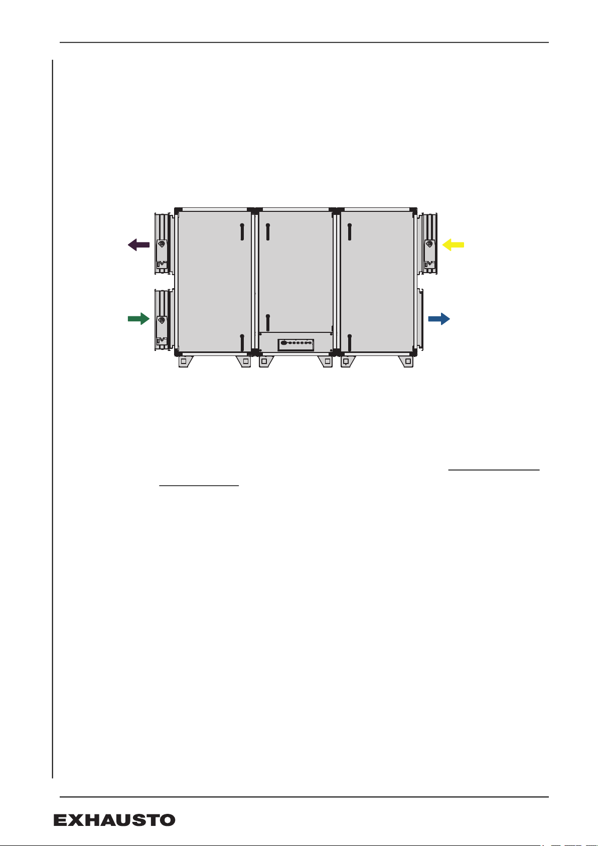
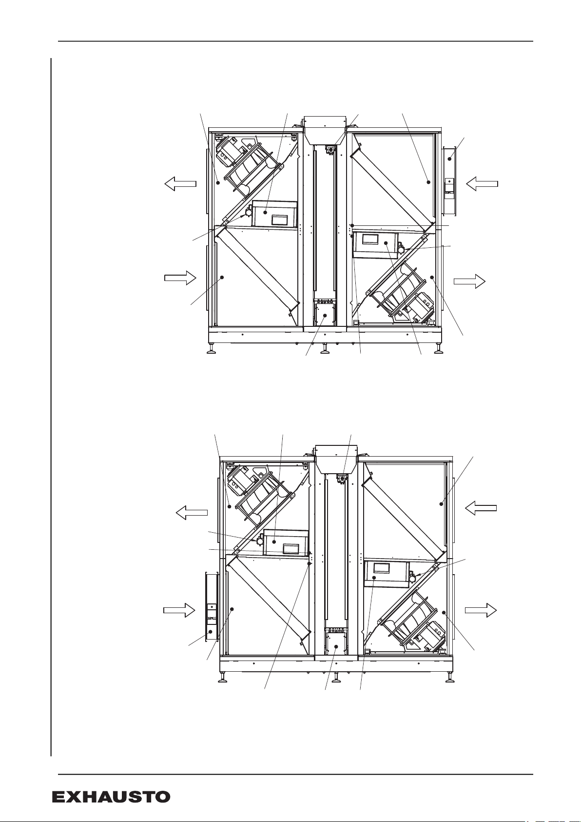
2.2.1 Fan placement VP1R
2.2.2 Fan placement VP1L
MC1
MC2
2,2,A
Supply air
2,1,A
Outdoor air
1,1,A
Extract air
1,2,A
Exhaust air
TE12
TE21
TE11
TE22
MPT1 MPT2
RHX2M
Pressure gauge
(-P11)
LS ALC
MPT3
Pressure gauge (-P22)
RD14193GB-01
RD14194GB-01
MC1
MC2RHX2M
2,2,A
Supply air
2,1,A
Outdoor air
1,1,A
Extract air
1,2,A
Exhaust air
TE12
TE21
TE11
TE22
MPT1
MPT2
LS ALC
Pressure gauge
(-P11)
Pressure gauge (-P22)
MPT3

3006324-2021-12-14.fm Connection
8/44
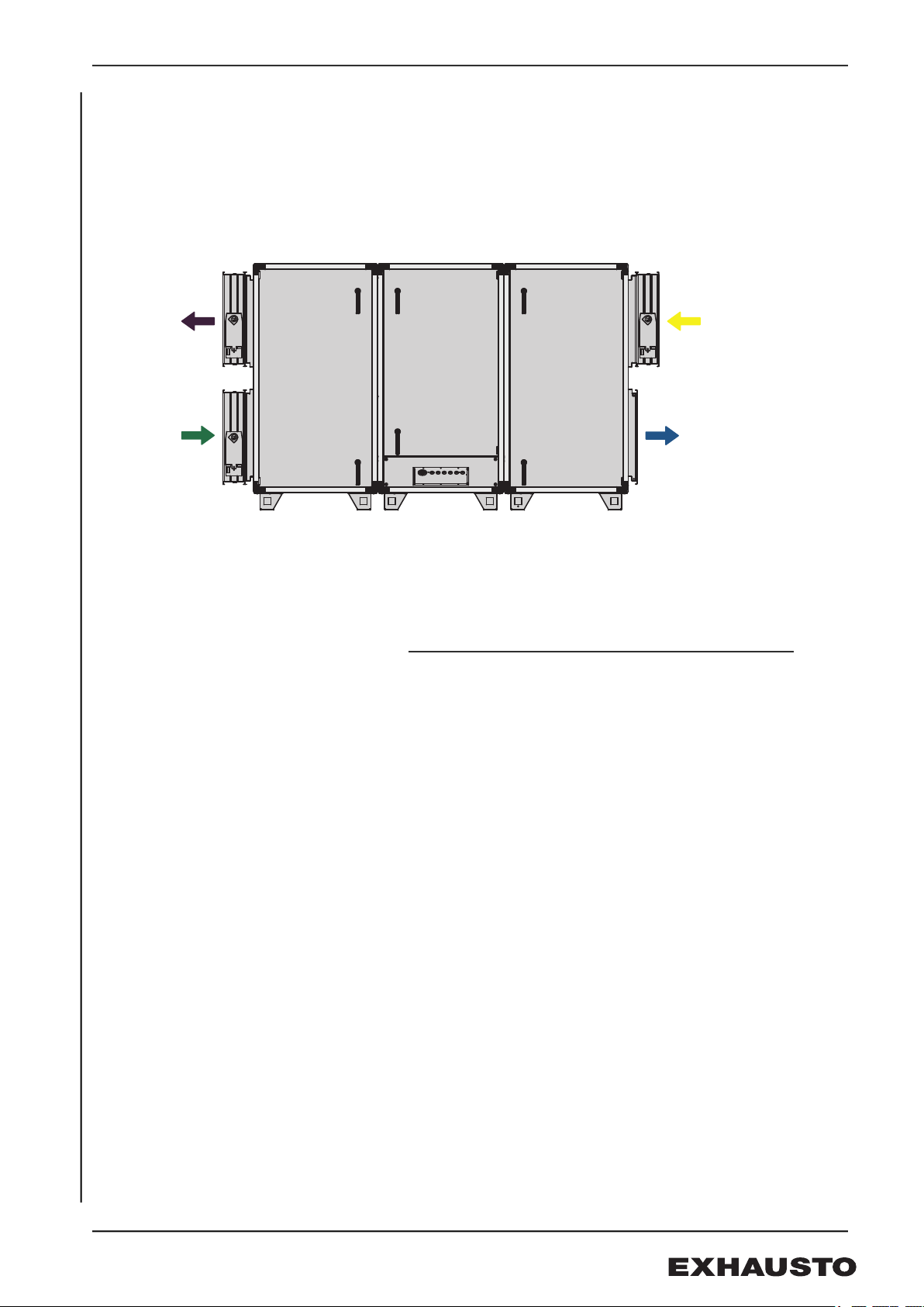
2.2.3 Fan placement VP2R
2.2.4 Fan placement VP2L
MPT3
RD14196GB-01
MC1
MC2 RHX2M
2,2,A
Supply air
2,1,A
Outdoor air
1,1,A
Extract air
1,2,A
Exhaust air
TE12
TE21
TE11
TE22
MPT1
MPT2
LS ALC
Pressure gauge
(-P11)
Pressure gauge (-P22)
MPT3 MC1
MC2
2,2,A
Supply air
2,1,A
Outdoor air
1,1,A
Extract air
1,2,A
Exhaust air
TE12
TE21
TE11
TE22
MPT1
MPT2
RHX2M
Pressure gauge
(-P11)
LS ALC
Pressure gauge (-P22)
RD14195GB-01

1. DK - Produkt information
1.1 Generelt
Denne tillægsvejledning beskriver montage af Automatisk Lækagekontrol (ALC), mel-
lem EXact2 main board og Belimo Modbus aktuatoren (LS ALC spjældmotoren på
fraluft) samt generelle driftsforhold og forbehold.
1.2 Anvendelse
ALC er en funktion, som forhindrer lækage i aggregater (AHU) med roterende varme-
veksler. ALC måler, kontrollerer og justerer kontinuerligt trykforskellen mellem tilluft- og
fraluftstrengen for at sikre, at der ikke recirkulerer forurenet luft til den rene luft i ventila-
tionsaggregatets tilluftstreng.
VIGTIGT!
ALC er konfigureret i HMI fra fabrik. Der skal kun tilsluttes LS ALC spjæld til EXact2
main board, se afsnit 2. Tilslutning.
1.3 Forudsætninger
ALC er muligt at konfigurere og aktivere i applikationer med:
• Roterende varmeveksler.
• Modbus styret spjæld i fraluft.
• Tryktransmitter monteret mellem tilluft og fraluft i rotorsektion.
• Renblæsningszone.
• EXact2 Software version 3.11.1.0 eller nyere.
1.4 Forbehold
ALC er ikke muligt i applikationer styret af:
• Konstant motorhastighed / CO2 / RLQ / RH.
• For anden automatik.
1.5 Drifts Funktion
Princippet i ALC funktionen er at holde et minimum undertryk i fraluftssiden (udsug-
ningssiden) af den roterende varmeveksler i forhold til tilluftssiden (Friskluftsiden) på 20
Pa.
Hvis differencetrykket på grund af dynamiske trykændringer bevæger sig imod en lave-
re værdi end 20 Pa, vil fraluftspjældet gradvist lukke imod minimum for at opretholde det
positive differencetryk.
3006324-2021-12-14.fm DK - Produkt information
10/44
1.6 Drifts forudsætninger
• Maksimal kanaltryktab (udeluft): 100 Pa ved maksimum ERP luftmængde.
• Minimum kanaltryktab (fraluft): 150Pa ved maksimum ERP luftmængde.
• Maksimal tilladelig ubalance i luftmængde mellem tilluft og fraluft: 50 %.
BEMÆRK!
Hvis driftsforudsætningerne ikke overholdes, kan der forkomme ustabilitet og/eller læ-
kage fra fraluft til tilluft.
Afbryd ALC
VIGTIGT! Det anbefales kun at slukke anlægget ved service og vedligeholdelse, da
der under opstart kortvarigt kan forekomme lækage.
RD14197DK-01
Minimum
tryktab:
150 Pa
Maximum
tryktab:
100 Pa
Table of contents
Languages:
Other Exhausto Control System manuals

Exhausto
Exhausto EXact2 VEX240 series User manual

Exhausto
Exhausto EXact2 VEX240 series Installation guide

Exhausto
Exhausto VEX260HX User manual

Exhausto
Exhausto EXact2 VEX240 series Installation guide

Exhausto
Exhausto VEX200 series Installation guide

Exhausto
Exhausto VEX150CF H User manual

Exhausto
Exhausto VEX320C User manual

Exhausto
Exhausto EXact2 HMI2-350-TOUCH Installation guide

Exhausto
Exhausto VEX100 Series User manual

Exhausto
Exhausto VEX320CX User manual


