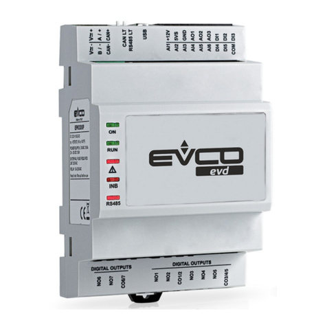
Evco Vcolor 679 User guide

EVCO S.p.A. Vcolor 679/689 | Installer manual ver. 1.0 | Code 144VC679E104
page
1
of
70
Vcolor 679/689
Controllers for retarding-proofing or proofing
cabinets and rooms with customised graphic skin
EN LISH
INSTALLER MANUAL ver. 1.0
CODE 144VC679E104

EVCO S.p.A. Vcolor 679/689 | Installer manual ver. 1.0 | Code 144VC679E104
page
of
70
Important
Read this document carefully before installation and before using the device and take all the prescribed precautions. Keep this
document with the device for future consultation.
Only use the device in the ways described in this document. Do not use the device as a safety device.
Disposal
The device must be disposed of according to local regulations governing the collection of electrical and electronic equipment.

EVCO S.p.A. Vcolor 679/689 | Installer manual ver. 1.0 | Code 144VC679E104
page
3
of
70
Contents
1 INTRODUCTION .................................................... 4
1.1 Introduction ......................................................... 4
1. Models available and main features ......................... 5
MEASUREMENTS AND INSTALLATION ...................... 8
.1 Format features .................................................... 8
. Control module measurements and installation ......... 8
.3 User interface measurements ................................. 8
.4 User interface installation ...................................... 9
.5 EVC 0P5 N9XXX10 – EVC 0P5 N9XXX1 expansion
module measurements and installation .................. 10
.6 Installation precautions ....................................... 10
3 ELECTRICAL CONNECTION ................................... 11
3.1 Vcolor 679/689 M electrical connection .................. 11
3. Vcolor 679/689 L electrical connection................... 1
3.3 Precautions for electrical connection ...................... 13
4 RETARDING-PROOFING OR PROOFING OPERATION 14
4.1 Initial information ............................................... 14
5 FIRST-TIME USE ................................................. 14
5.1 Operating modes ................................................ 14
5. Operating the device ........................................... 14
6 NAVIGATION ...................................................... 16
6.1 Initial information ............................................... 16
6. Home screen ...................................................... 16
6.3 Cycle running screen ........................................... 17
6.4 Screen saver ...................................................... 0
6.5 Settings screen .................................................. 0
6.6 Users ................................................................
6.7 Welcome page ....................................................
7 OVERVIEW OF THE FUNCTIONS ............................ 3
7.1 Automatic cycle .................................................. 3
7. Manual cycles ..................................................... 7
8 MAIN FUNCTIONS ............................................... 8
8.1 Automatic cycle .................................................. 8
8. Heating cycle ..................................................... 3
8.3 Cooling cycle (for retarding-proofing only) ............. 33
8.4 Pre- cooling cycle (for retarding-proofing only) ....... 34
8.5 Recipe book ....................................................... 35
9 REGULATIONS .................................................... 36
9.1 Pre-cooling (for retarding-proofing only) ................ 36
9. Temperature regulation ....................................... 36
9.3 Humidity regulation ............................................ 37
10 LOAD MANAGEMENT ........................................... 39
10.1 ON-OFF / variable speed compressor management
(for retarding-proofing only) ................................. 39
10. Pump-down management (for retarding-proofing
only) ................................................................. 39
10.3 Evaporator fan management ................................ 39
10.4 Defrost management (for retarding-proofing only) .. 40
10.5 Heater management ............................................ 40
10.6 Steam generator output management ................... 41
10.7 Humidifier output management ............................ 41
10.8 Dehumidification management.............................. 4
10.9 Condenser fan management (for retarding-proofing
only) ................................................................. 4
10.10 Cabinet light management ................................... 4
10.11 Door frame management (for retarding-proofing
only) ................................................................. 4
10.1 On/stand-by relay configuration ............................ 4
10.13 Output testing .................................................... 4
10.14 Testing cycle ...................................................... 43
11 CONNECTIVITY ................................................... 44
11.1 Initial information ............................................... 44
11. EPoCA cloud platform .......................................... 45
1 USB PORT MANAGEMENT ..................................... 46
1 .1 Available functions .............................................. 46
13 ALARMS ............................................................. 47
13.1 Active alarms ..................................................... 47
13. List of alarms ..................................................... 48
14 PARAMETERS...................................................... 51
15 ACCESSORIES .................................................... 63
15.1 4 relay expansion ................................................ 63
15. Phase cutting speed regulator ............................... 63
15.3 EVCO Inverter .................................................... 63
15.4 Safety transformer .............................................. 64
15.5 Non-optoisolated RS-485/USB serial interface ........ 64
15.6 USB plug for panel installation .............................. 64
15.7 Connecting cables ............................................... 64
15.8 4GB USB flash drive ............................................ 64
15.9 EVlinking Wi-Fi RS-485 module ............................. 65
15.10 IoT EV3 Web gateway.......................................... 65
15.11 NTC temperature and humidity probe .................... 65
15.1 Humidity transducer 4÷ 0 mA .............................. 65
16 TECHNICAL SPECIFICATIONS ............................... 66
16.1 Technical data .................................................... 66

EVCO S.p.A. Vcolor 679/689 | Installer manual ver. 1.0 | Code 144VC679E104
page
4
of
70
1INTRODUCTION
1.1 Introduction
Vcolor 679/689 is a controller for retarding-proofing or proofing cabinets and rooms which delivers high performance and precision
regulation, thanks to a modulating output which gives control of up to ten evaporator fan speeds. The evaporator fan can also be
modulated using an EVCO inverter. In the 689 models, the modulating output can also be set to control variable speed compressors.
By simply setting a parameter, the controller can be configured to manage retarding-proofing and proofing automatic cycles. Variables
such as temperature, humidity, fan intensity and duration can be managed independently for each phase. As well as three-phase
proofing cycles (re-awakening, proofing and baking delay), with blocking and holding added in the retarding-proofing cycles, there are
also manual cycles such as heating for proofing and cooling/pre-cooling/heating for retarding-proofing.
The controller’s innovative programmable platform gives manufacturers the freedom to personalise the graphic skin and programmes
and add new languages. All they have to do is compile an ODS file and upload it using a flash drive to the USB port on the user
interface. Users can store up to 100 programmes, match them to a set of preloaded images and move them to the favourites.
Users can interact remotely with their equipment and start up/stop working cycles using the EPoCA® cloud platform with Wi-Fi or
Ethernet connectivity (which also enables alternative or parallel control through MODBUS TCP). For more details, compare all the
connectivity options in the Technical Data table and consult the Management and Monitoring Products/Systems and the Connectivity
Products/Devices sections of our website.
The controller has an open frame board and a remote user interface which consists of a 5-inch (M) or 7-inch (L) capacitive TFT touch-
screen graphic display in glass which is installed horizontally either semi-recessed into the front or flush with the panel.

EVCO S.p.A. Vcolor 679/689 | Installer manual ver. 1.0 | Code 144VC679E104
page
5
of
70
1.2 Models available and main features
The table below shows the main features of the models available.
MAIN FEATURES
KITS OPTIONS
Vcolor 679 M & L
with PWM output
Vcolor 689 M & L
with 0-10 V
output
I/O expansion
module
Speed
regulator Inverter
EVC20P52N9XXX12*
EVDFAN1
(for 679
models only)
Compact,
Slim and
Slim Power
Power supply
Control module 115... 30 VAC 115... 30 VAC
User interface Powered by the
control module
Powered by an
external
transformer
1 VAC/ 0VA
Optional modules 115... 30 Vac 30 Vac 30 Vac
Analogue inputs
Cabinet probe (PTC/NTC) • •
Evaporator probe (PTC/NTC) • •
Condenser probe (PTC/NTC) • •
Humidity transducer (4- 0 mA) • •
Temperature (NTC)/humidity
EVHTP5 0 probe • •
Digital inputs (for NO/NC
contact)
Door switch • •
Configurable multi-purpose 1
(default high pressure alarm) • •
Configurable multi-purpose
(default pump-down completed) • •
Configurable multi-purpose 3
(default low pressure alarm) • •
Modulating output
Can be configured as 0-10 V to
module the evaporator fan or as
frequency for variable speed
compressors
•
Can be configured as PWM for
EVDFAN1 speed regulator
(evaporator fan)
•

EVCO S.p.A. Vcolor 679/689 | Installer manual ver. 1.0 | Code 144VC679E104
page
6
of
70
MAIN FEATURES
KITS OPTIONS
Vcolor 679 M & L
with PWM output
Vcolor 689 M & L
with 0-10 V
output
I/O expansion
module
Speed
regulator Inverter
EVC20P52N9XXX12*
EVDFAN1
(for 679
models only)
Compact,
Slim and
Slim Power
Digital outputs (sealed relays A
res. @ 250 VAC)
Configurable K1 (default
compressor) 16 A 16 A
Configurable K (default cabinet
light) 8 A 8 A
Configurable K3 (default humidifier) 8 A 8 A
Configurable K4 (default
dehumidifier) 8 A 8 A
Configurable K5 (default defrost) 8 A 8 A
Configurable K6 (default heater) 16 A 16 A
Configurable K7 (default steam
generator) 16 A 16 A
Configurable K8 (default pump-
down) 8 A 8 A
Configurable K9 (default door
heater) 8 A 8 A
Configurable K10 (default
sanitation) 30 A
Configurable K11 (default on/stand-
by) 16 A
Configurable K1 (alarm) 8 A
Configurable K13 (default condenser
fan) 16 A
Communications ports
RS-485 MODBUS • •
USB • •
Connectivity
RS-485 MODBUS RTU (built-in) • •
Wi-Fi EPoCA/MODBUS TCP (optional
through the EVlinking Wi-Fi module
powered by controller)
• •
Ethernet EPoCA/MODBUS TCP
(optional through EV3 Web
gateway)
• •

EVCO S.p.A. Vcolor 679/689 | Installer manual ver. 1.0 | Code 144VC679E104
page
7
of
70
MAIN FEATURES
KITS OPTIONS
Vcolor 679 M & L
with PWM output
Vcolor 689 M & L
with 0-10 V
output
I/O expansion
module
Speed
regulator Inverter
EVC20P52N9XXX12*
EVDFAN1
(for 679
models only)
Compact,
Slim and
Slim Power
Other features
Clock • •
Alarm buzzer • •
Management of automatic and
manual cycles • •
Fan intensity management • • •
Saving HACCP files • •
"Programmes" function • •
* The code refers to the I/O expansion module with HC sealed relays
For more information see section 16 “TECHNICAL SPECIFICATIONS”.
The table below lists the purchasing codes of the available models:
Purchasing codes
Models with PWM output
Vcolor 679 M (control module + 5” user interface):
EVCMC679N9EH (flush fit installation)
EVCMC679N9EFH (semi-recessed installation)
Vcolor 679 L (control module + 7” user interface):
EVCLC679N9EH (flush fit installation)
EVCLC679N9EFH (semi-recessed installation)
Models with 0-10 V output
Vcolor 689 M (control module + 5” user interface):
EVCMC679N9EH (flush fit installation)
EVCMC689N9EFH (semi-recessed installation)
Vcolor 689 L (control module + 7” user interface):
EVCLC689N9EH (flush fit installation)
EVCLC689N9EFH (semi-recessed installation)
For more models, contact the EVCO sales network.

EVCO S.p.A. Vcolor 679/689 | Installer manual ver. 1.0 | Code 144VC679E104
page
8
of
70
2MEASUREMENTS AND INSTALLATION
2.1 Format features
The control module is available in a split version with an open frame board. User interfaces are available in 5- or 7-inch versions for
horizontal operation and have capacitive colour TFT touch-screen graphic displays.
2.2 Control module measurements and installation
Installation of the control module is on a flat surface with spacers.
2.3 User interface measurements
The user interface is available in the model which is installed flush and the model which is semi-recessed into the front. The
measurements vary according to the model, as illustrated below in mm (in).
Vcolor 679/689 M interface

EVCO S.p.A. Vcolor 679/689 | Installer manual ver. 1.0 | Code 144VC679E104
page
9
of
70
Vcolor 679/689 L interface
2.4 User interface installation
Depending on the model, installation can be:
-flush, from behind the panel with threaded studs (not provided) welded to hold it in place;
-semi-recessed, from the front of the panel with spring clips to hold it in place.

EVCO S.p.A. Vcolor 679/689 | Installer manual ver. 1.0 | Code 144VC679E104
page
10
of
70
2.5 EVC20P52N9XXX10 – EVC20P52N9XXX12 expansion module measurements and
installation
The diagram below shows the measurements of the 4 relay expansion. Installation is on a flat surface with spacers.
2.6 Installation precautions
- Ensure that the working conditions for the device (operating temperature, humidity, etc.) are within the set limits. See
section 16 “TECHNICAL SPECIFICATIONS”.
- Do not install the device close to heat sources (heaters, hot air ducts, etc.), equipment with a strong magnetic field (large
diffusers, etc.), in places subject to direct sunlight, rain, damp, excessive dust, mechanical vibrations or shocks.
- Any metal parts close to the control module must be far enough away so as not to compromise the safety distance.
- In compliance with safety regulations, the device must be installed properly to ensure adequate protection from contact
with electrical parts. All protective parts must be fixed in such a way as to need the aid of a tool to remove them.
This manual suits for next models
1
Table of contents
Other Evco Controllers manuals

Evco
Evco Vcolor 379 User guide

Evco
Evco EV3B33N7VXRX04 User manual

Evco
Evco Vcolor 318 M User guide

Evco
Evco EV3B94 User manual

Evco
Evco c-pro 3 NODE kilo User manual

Evco
Evco c-pro 3 nano CHIL Instructions for use

Evco
Evco C-pro 3 giga User manual

Evco
Evco EVFTFT618 User guide

Evco
Evco EV3 CHIL User manual

Evco
Evco c-pro 3 OEM User manual
Popular Controllers manuals by other brands

Digiplex
Digiplex DGP-848 Programming guide

YASKAWA
YASKAWA SGM series user manual

Sinope
Sinope Calypso RM3500ZB installation guide

Isimet
Isimet DLA Series Style 2 Installation, Operations, Start-up and Maintenance Instructions

LSIS
LSIS sv-ip5a user manual

Rockwell Automation
Rockwell Automation 1769-L31 installation instructions