Estarmodels SUPER DECATHLON User manual

SUPER DECATHLON
INSTRUCTIONS
www.estarmodels.com
zKIT INCLUDES zITEMS NEEDED TO COMPLETE
Full size plan
Lasercut parts
1.5mm(1/16”)xL600mm(24”) balsa : 1sheet
1.5mm(1/16”)xL500mm(20”) balsa : 2sheets
1.5mm(1/16”)xL430mm(17”) balsa : 2sheets
3.0mm(1/8”)xL560mm(22.4”) balsa : 1sheet
3.0mm(1/8”)xL465mm(18.6”) balsa : 6sheets
3.0mm(1/8”)xL370mm(14.8”) balsa : 1sheet
5.0mm(3/16”) xL520mm(20.5”) balsa stick : 2ea
5.0mm(3/16”) xL410mm(16.1”) balsa wing jig : 1ea
1.8mm(5/64”)xL150mm(6”) plywood :1sheet
3.0mm(1/8”)xL600mm(24”) plywood :2sheets
Vacuum formed Cowl & Wheel pants.
Motor mount 10x10x75mm
Landing gears(2ea)
3mm screws(4ea), 2mm screws(20ea)
Tail gear
Neodymium Manetics (4ea)
CA hinge
Pushrods(4ea) for Rudder, Elevator, Ailerons
Clear plastic for Windshield
Instructions and Stickers.
GWS EPS-400C-DS(3:1) or
BL motor (4~5.33:1 geared,
10~13A)
ESC (15A)
GWS slow prop 9070
Li-Poly 11.1V 1500~1800mAh
Battery w/Li-Poly charger
Micro or Mini Receiver
(4~6 channel)
4 submicro Servos
(Hitec HS-55 / Futaba S3108 /
GWS pico servos, or equivalant)
& servo extension cords.
2~3 rolls of covering film.
(Solite film, or equivalant)
50mm Wheels, Wheel Collars
(4ea) and EZ connectors (4ea)
Page 1
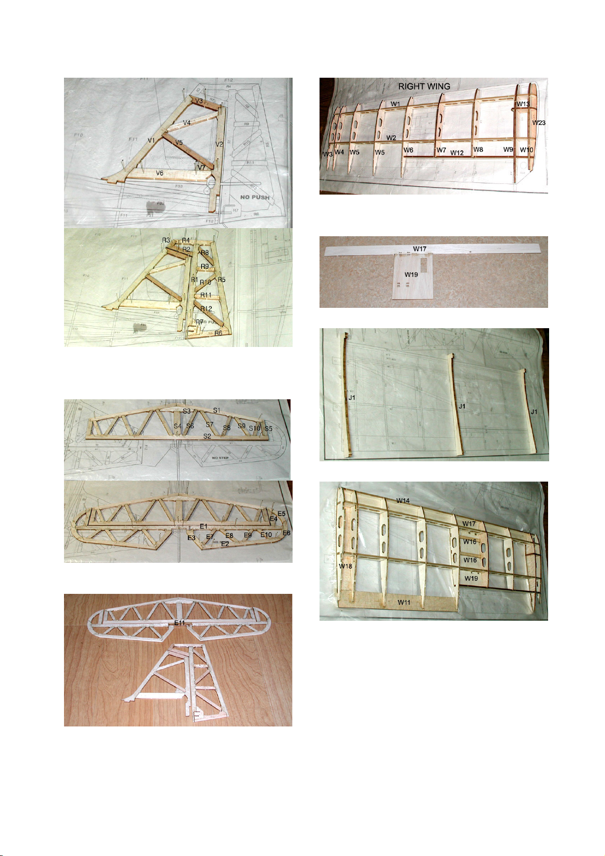
zTAIL CONSTRUCTION zWING CONSTRUCTION
1. Lay the waxed paper or PVC film over the plan.
Pin the Vertical Fin parts(V1-V7) and Rudder parts(R1-
R12)on the plan.
Glue the parts with thin CA.
2. Pin the Stabilizer parts(S1-S10) and Elevator parts(E1-
E10) on the plan. Glue the parts with thin CA.
3. Join Elevators with the plywood part(E11).
Remove tail from the plan and apply thick CA glue at each
joints for reinforcing.
1. Temporary assemble ribs(W3-W10), spars(W1,W2), tailing
edge(W12) and wingtip parts(W13, W23) on the plan. Pins
and glues are not required in this step.
2. Glue lower sheets(W17, W19) together.
3. Pin the wing jig(J1) on the plan.
4. Lay trailing edge(W11), sub leading edge(W14), pre-
assembled lower sheets(W17, W19), servo trays(W16), lower
wingroot sheet(W18) and pre-assembled parts on the jig.
After fix with pins, glue each other with thick CA.
Page 2

5. Glue wing joiners(W15) with thin CA, then apply thick CA
glue.
6. Glue upper sheets(W20, W21) with thick CA.
7. Remove wing from the wing jig, glue the lower
sheets(W25, W26).
8. Glue wingtip part(W22).
9. Glue leading edge(W24). apply thick CA glue at each
joints for reinforcing.
10. Assemble the other side wing.
11. Pin the aileron parts(A1-A5) on the plan and glue each
other.
12. Carefully sand surfaces.
Page 3

zFUSELAGE CONSTRUCTION
1. Lay right side panel(F28) on the plan and temporary
assemble longerons(F13A-F16) and bulkheads(F6, F7).
Pins and glues are not required in this step.
2. Glue landing gear mounts(B13, B14) together.
3. assemble landing gear mounts, bulkhead(F6A) and servo
bed(B11).
4. Temporary assemble longerons(F13A-F16) and
firewall(F5).
Make sure to pay attention to all bulkheads, the numbers
should be facing forward.
5. Assemble left side panel(F28).and glue with thin CA.
Apply thick CA glue at each joints for reinforcing.
6. Temporary assemble cockpit post(F24) and wing
attachments(F27).
7. Assemble wing joiner bracket(F25, F26) and upper
fuselage longerones(F22R, F22L) and glue with thick CA.
8. Cut longerons ends as shown on the drawing.
Page 4

9. Temporary assemble rear fuselage bulkheads(F8-F11)
and longerones(F23, F13B, F19).
10. Glue fore and rear fuselage together.
11. Glue window frame(F29).
After sight check down the fuselage to insure against twist,
then apply thick CA at each joints for reinforcing.
12. Glue cockpit diagonal parts(F34, F35).
13. Glue turtle deck frame(F17, F18).
14. Wrap and glue side panels(F28).
15. Wrap and glue turtle deck(F30).
16. Glue wing joiner bracket cover(F25A, F26A).
Page 5

17. Glue bulkhead(F12) and panels for pushrod exit(F31,
F32).
18. Glue servo tray(B12) and fuselage bottom(F37).
19. Glue sub longerons(F21A, F23A).
20. Assemble stabilizer bed(F33, F33A).
21. Shape and sand stabilizer bed.
22. Assemble hatch parts(H1-H4, H8) on the plan and glue
them.
23. Finish hatch parts(H5-H7).
24. Assemble motor mount box(F2-F4).
25. Glue rear window brace(F38).
26. Glue fore and rear stut (B8, B9).
Tie with thread and reinforce with thin CA.
Page 6

27. Assemble and glue strut mounts(B1-B3, B6-B7).
28. Test assemble airframe. (This step is for your pleasure in
looking.)
29. Assemble plywood tail wheel.
30. Paint cockpit area, strut parts, landing gear and tail
wheel.
31. Fix tail gear and wheel.
32. Insert and glue plastic pipes for elevator and rudder
pushrods.
33. Glue cowl mount(B16-B17).
Page 7

zCOVERING AND EQUIPMENT INSTALLATION
1. Cover Decathlon with your trim choice.
2. Install and glue neodymium magnetics with thin CA.
3. Glue the plywood dowel of hatch(H9).
4. Cut CA hinges as shown above.
5. Install and glue aileron and rudder plywood horns. (Do not
glue elevator horn in this step.)
Apply thin CA to the horns for reinforcing.
Make hinge slots and pre-install hinges. (Do not glue hinges
in this step.)
6. Insert and glue strut mounts(B1-B7) with thick CA.
7. Insert landing gear.
Page 8

8. Cover landing gear retainer(B15) and fix with screws.
9. Glue stabilizer and vertical fin to the fuselage with thick
CA. (Horizontal tail must be paralleled with wing and
vertical fin must be at right angle to horizontal tail.
Wings must be installed temporarily to align them.)
Insert elevator pushrod to the horn and then glue hinges
with small amount of thin CA.
Insert rudder pushrod to the horn and then glue hinges with
small amount of thin CA.
10. Install elevator and rudder servos.
11. Install aileron servos and connect pushrods.
12. Cut clear plastic windshield and glue.(refer to template on
the drawing). Cover side windows with clear film.
13. Assemble dummy landing gear.
14. Draw cutting line. (4mm above from the bottom)
15. Cut wheelpants.
16. Bond together with thin CA.
Page 9

17. Glue Plywood rings with thin CA and put color stickers
on.
18. Install wheelpants and wheels to the landing gear.
19. Glue motor mount stick and install motor.
20. Draw cutting line (4mm above from the bottom) and cut
cowl.
21. Assemble cowl with screws.
22. Paint or cover film after shape and glue F39 parts.
23. Insert and fix struts to the wings with screws.
24. Assemble wing and fix with screws. Enjoy flying!
Control Throws
The following control throws are recommended starting points.After
you are familiar with this plane, you may increase, or decrease.
Ailerons : 16mm(5/8”) up, 12mm(3/8”) down.
Elevator : 14mm(9/16”) up and down.
Rudder : 19mm(3/4”) right and left.
Page 10
Table of contents
Other Estarmodels Toy manuals


