Ericsson MINI-LINK PT 2010 ETSI Parts list manual

Technical Description
MINI-LINK PT 2010 ETSI
DESCRIPTION
1/221 02-CSH 109 172/1-V1 Uen E

Copyright
© Ericsson AB 2010–2012. All rights reserved. No part of this material may be
reproduced in any form without the written permission of the copyright owner.
Disclaimer
The contents of this document are subject to revision without notice due to
continued progress in methodology, design and manufacturing. Ericsson shall
have no liability for any error or damage of any kind resulting from the use
of this document.
1/221 02-CSH 109 172/1-V1 Uen E | 2012-11-07

Contents
Contents
1 Introduction 1
1.1 General 1
1.2 Scope 2
1.3 Revision Information 2
2 Network Overview 2
3 System Overview 3
4 Ethernet Traffic Handling in MINI-LINK PT 2010 6
4.1 Ethernet WAN Buffer 6
4.2 Native Ethernet 7
5 MINI-LINK PT 2010 Functions – Radio Link 8
5.1 Hitless Adaptive Modulation 8
5.2 Transmit Power Control 10
6 MINI-LINK PT 2010 Functions – Ethernet 12
6.1 Ethernet Functional Flow in MINI-LINK PT 2010 15
6.2 Quality of Service Support 26
6.3 Performance Monitoring 28
6.4 Delay 29
7 MINI-LINK PT 2010 Functions – Synchronization 29
7.1 Overview 29
7.2 Synchronization Technologies 30
8 MINI-LINK PT 2010 Hardware 32
8.1 Packet Terminal 32
8.2 Antennas 34
9 Management 36
9.1 DCN 36
9.2 Management Tools and Interfaces 38
9.3 Configuration Management 40
9.4 Fault Management 41
9.5 Performance Management 42
1/221 02-CSH 109 172/1-V1 Uen E | 2012-11-07

Technical Description
9.6 Hardware Management 44
9.7 Software Management 44
9.8 License Management 44
10 Accessories 45
10.1 Cables and Cable Clamps 45
10.2 Hybrid Cable 47
10.3 Optical Cable Distribution System 48
10.4 SFP 49
11 Technical Specifications 50
11.1 Power Supply Requirements 50
11.2 Environmental Conditions 50
11.3 Dimensions and Weight 51
11.4 Traffic Interfaces 51
1/221 02-CSH 109 172/1-V1 Uen E | 2012-11-07

Introduction
1 Introduction
1.1 General
The purpose of this description is to give the reader detailed information on
MINI-LINK PT 2010, both from a technical and functional perspective.
MINI-LINK PT 2010 is a complete microwave modem and radio unit with the
capability of handling IP and Ethernet traffic using all the required frequencies
in the 6–42 GHz range.
MINI-LINK PT 2010 is an all-outdoor Packet Terminal, housed in a radio unit
case. It is suitable for repeater and end sites due to the small footprint and
the easy mountability.
Some functions described in this document are subject to license handling, that
is, a soft key is required to enable a specific function.
1.1.1 Packet Transport in Microwave Networks
Compared to other transmission technologies, a microwave link can be
characterized as a limited bandwidth connection. This implies that microwave
equipment must be designed to enable maximum packet payload throughput
in the available bandwidth over the radio interface. The following features
improve the link efficiency:
Congestion Handling/Priority Queues
For connections with limited bandwidth it is important to support a mechanism
that prioritizes high priority packets when a connection is congested.
Adaptive Modulation
Adaptive modulation seeks continuously to use the modulation alternatives that
will maximize throughput under different conditions.
Low Residual BER
Microwave links operate with large fade margins and forward error correction
resulting in low residual BER level, typically 10-12.
Buffering Capabilities
Buffering capacities are 64 MB in the WAN direction. Each TC can use up
to 128 blocks, of 64 kB each.
1
1/221 02-CSH 109 172/1-V1 Uen E | 2012-11-07
Technical Description
1.2 Scope
The purpose of this description is to support the reader with detailed information
on included products and accessories, from technical and functional points
of view.
1.3 Revision Information
This release of the document includes an update of the MINI-LINK PT 2010
functions within the scope of release MINI-LINK PT 2010 1.2.
The following changes have been made since the last release:
• Information regarding compatible SFPs has been updated.
• Information regarding capacity has been updated.
2 Network Overview
DC -48V 2A MAX
+ DC:2 - + DC:1 -
ERICSSON
MINI-LINKSP 110 Fault
Power
Oper
Sync
USBO&M O&M SYNC2
USERI/O SYNC 1
1 1 2 3 4 TR:1A-1B TR:2A-2B TR:3A-3B TR:4A-4B3
2
10/100/1000Base-T / 100/1000 Base-X
4
10/100/1000Base-T
E1/DS1
FE/GE
PT 2010 PT 2010
MINI-LINK SP 110
MINI-LINK PT 2010
6-42 GHz, 1+0,
406 Mbps
Mixed MINI-LINK
PT 2010 /
MMU2 H / RAU X
6-42 GHz, 1+0,
406 Mbps
n × E1
3G
2G
LTE
PT 2010 PT 2010
RAU X
PT 2010
MINI-LINK TN
MINI-LINK PT 2010
6-42 GHz, 1+0,
406 Mbps
LTE
LTE
14017
Figure 1 MINI-LINK PT 2010 Network Scenario Overview
Using the MINI-LINK PT 2010 product to build your Ethernet network means
that you have a broad range of alternatives to choose from. Within the
21/221 02-CSH 109 172/1-V1 Uen E | 2012-11-07

System Overview
MINI-LINK PT 2010 product offering there is support for Ethernet transport with
different bandwidth and capacity options over both radio and fixed connections.
MINI-LINK PT 2010 offers the size and capacity to meet the needs of both last
mile access and first aggregation point, in a mobile backhaul network.
3 System Overview
This section gives a brief introduction to the system and its components.
3
1/221 02-CSH 109 172/1-V1 Uen E | 2012-11-07

Technical Description
15502
15GHz
15GHz
Power Cable
Optical Fiber Cable
O&M
TRAFFIC/ALIGNMENT POWER
TRAFFIC/ALIGNMENT POWER
O&M
XPIC
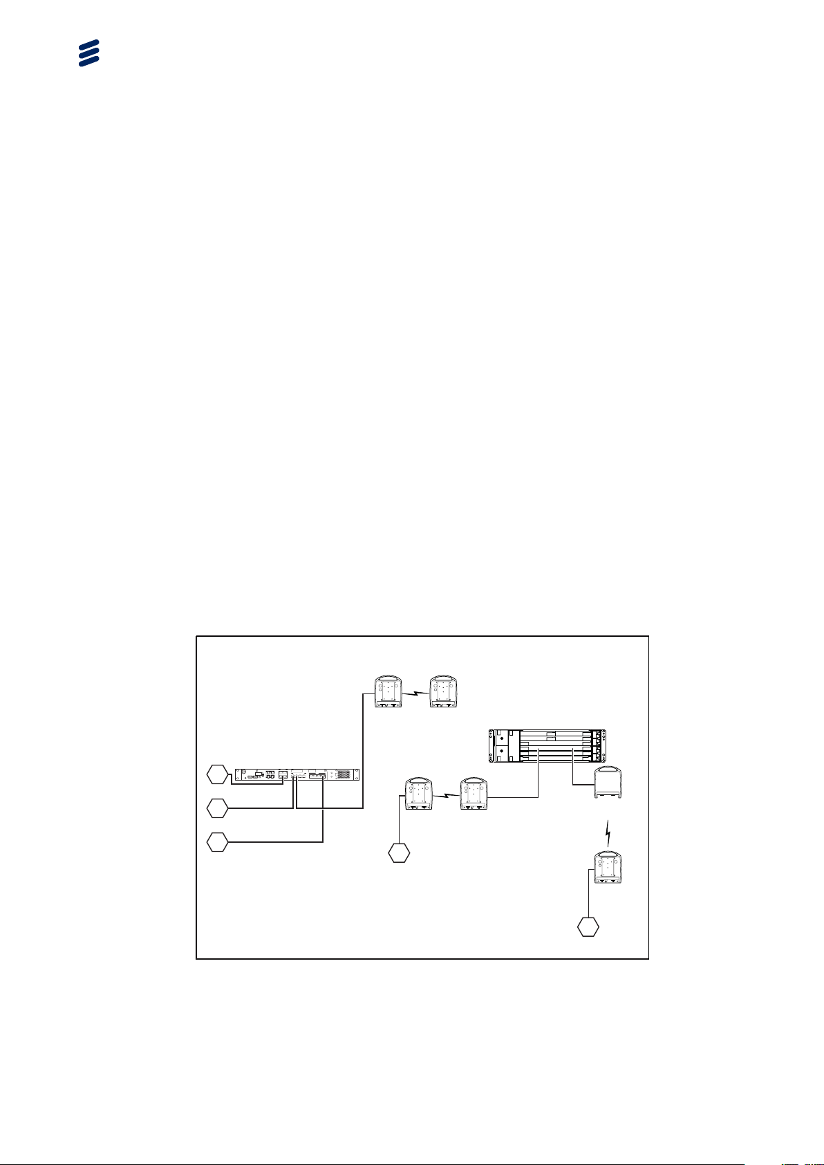
Figure 2 System Overview
41/221 02-CSH 109 172/1-V1 Uen E | 2012-11-07
System Overview
MINI-LINK PT 2010 is a stand-alone product integrating the system platform
providing traffic and system control, with microwave transmission from 8 to
406 Mbps.
MINI-LINK PT 2010 operates within the 6 to 42 GHz frequency bands, using
4, 16, 32, 64, 128, 256, and 512 QAM modulation schemes, also supporting
Hitless Adaptive Modulation.
MINI-LINK PT 2010 is an all-outdoor system. It is connected with a DC supply
voltage and an optical fiber cable.
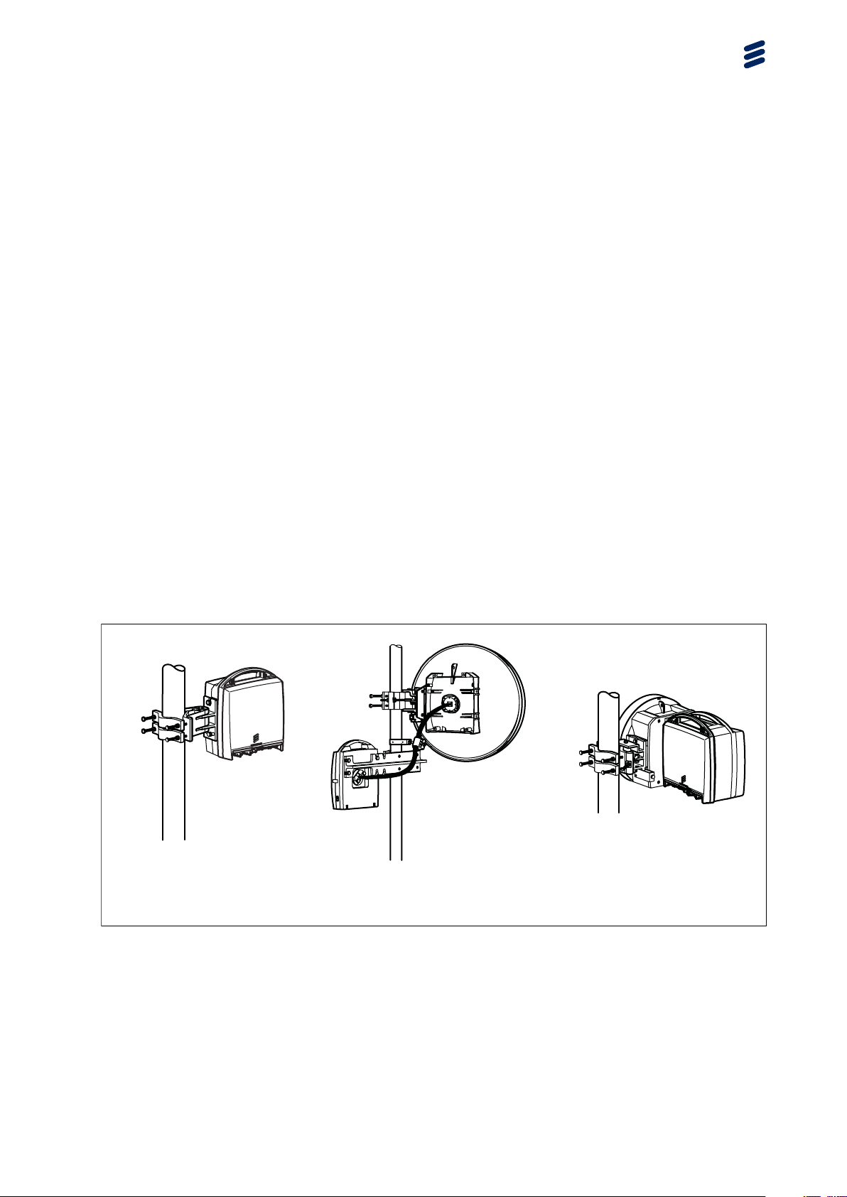
For dual MINI-LINK PT 2010 installation systems, two Packet Terminals and
one or two antennas are used. When using one antenna, the two Packet
Terminals are connected to the antenna using a power splitter.
The Packet Terminal and the antenna are easily installed on a wide range of
support structures. The Packet Terminal is fitted directly to the antenna as
standard, integrated installation. The Packet Terminal and the antenna can
also be fitted separately and connected by a flexible waveguide. In all cases,
the antenna is easily aligned and the Packet Terminal can be disconnected and
replaced without affecting the antenna alignment.
The Packet Terminal is described in Section 8.1 on page 32.
The antennas are described in Section 8.2 on page 34.
15503
Dual installation with
integrated power splitter
1+0 terminal
separate installation
1+0 terminal
integrated installation
TRAFFIC/ALIGNMENT POWER
O&M
XPIC
O&M
O&M
XPIC
XPIC
Figure 3 MINI-LINK PT 2010s and Antennas in Different Installation Alternatives
5
1/221 02-CSH 109 172/1-V1 Uen E | 2012-11-07

Technical Description
4 Ethernet Traffic Handling in MINI-LINK
PT 2010
MINI-LINK PT 2010 supports all-IP and Native Ethernet simultaneously.
Ethernet traffic is sent over a hop as Ethernet over packet link (Native Ethernet).
The Ethernet LAN ports are described in Table 1.
Table 1 Ethernet LAN Port Properties
Ethernet LAN port properties Description
SFP modules SFP plug-in module is supported with
1 Gbps optical interface.
Standard frame sizes Up to 2,000 bytes when
used as an external interface
(IEEE802.3as-2006).
Up to 2,048 bytes when used as an
internal interface
Jumbo frames 9,216 byte frame size for data
applications
Connectors/cables Single/multi-mode fiber with LC
connector for the optical i/f.
4.1 Ethernet WAN Buffer
The WAN port buffer in MINI-LINK PT 2010 has been designed to handle
burst and congestion in order to provide a high link utilization and goodput for
high-speed data traffic.
Since extensive buffering has a negative impact on frame delay variation, it is
important to have the possibility to configure buffer/queue size for different
traffic classes independently.
This means that queues configured to handle delay variation sensitive traffic
such as synchronization traffic, shall be configured to be very short.
In contrast, for traffic queues for less delay variation sensitive traffic the
Transmission Control Protocol/Internet Protocol (TCP/IP) has a congestion
avoidance mechanism that is based on buffer utilization. In order to provide a
high link utilization and high TCP goodput, queues configured to handle this
type of traffic needs to be in the area of hundreds of milliseconds at the smallest
congestion point, equivalent to the network end-to-end Round-Trip time.
61/221 02-CSH 109 172/1-V1 Uen E | 2012-11-07
Table of contents
Other Ericsson Modem manuals

Ericsson
Ericsson HM210DP/DI User manual

Ericsson
Ericsson HM121di User manual

Ericsson
Ericsson GC 75 User manual

Ericsson
Ericsson HM200c/HM201c User manual

Ericsson
Ericsson F251m User manual

Ericsson
Ericsson C3607w User manual

Ericsson
Ericsson ZAT 19.2 User manual

Ericsson
Ericsson PipeRider HM200c User manual

Ericsson
Ericsson F5521gw Parts list manual

Ericsson
Ericsson HM220d User manual


