Eneo NLD-1422 User manual

Please read this manual thoroughly before use and keep it handy for future reference.
NLD-1422
22X PTZ III NETWORK DOME CAMERA
GB

2
Chapter 1 — Introd ction
1.1 Feat res
The dome camera and the keyboard controller, PC software makes up the building blocks for any
surveillance/security system. Using multiple keyboard controllers and multiple dome cameras, no
place is too large for monitoring. E tensible and fle ible architecture facilitates remote control
functions for a variety of e ternal switching devices such as multiple ers and DVRs.
• Built-in optical power zoom camera with True Night Shot function.
• Dual video streams simultaneously at full frame rate in all resolutions up to D1 (720X480 in
NTSC, 720X576 in PAL) using Motion JPEG and H.264 (or MPEG-4).
• Intelligent capabilities such as enhanced video motion detection
The encoder’s e ternal inputs and outputs can be connected to devices such as sensors and
relays, enabling the system to react to alarms and activate lights or open/close doors.
• Supports two-way audio
• Logs all user access, and lists currently connected users. Also, full frame rate video can be
provided over HTTPS.
• Interface Protocol: TCP/IP, UDP, IPv4/v6, HTTP, HTTPS, QoS, FTP, SNMP, uPnP, RTP,
RTSP, RTCP, DHCP, ARP
• 120 Preset positions with the individual Camera AE setup
• 4 Tours consist of Presets, Patterns, Auto Scans and other Tours can be programmed with
over 150 functions and Preset locations. While moving, each Preset scan can be watched in
smooth Vector Scan mode.
• 4 Auto Scans with the normal, the vector, and the random mode and the Endless Auto-Pan
with 13 speed steps.
• 4 Patterns (up to 200 second) and 4 Privacy Zones
• 8 Area Titles
• 1 Alarm input / 1 Alarm output
• Variable speed from 0.1°/sec to 380°/sec
Three Variable speed (SLOW, NORMAL, TURBO)
Turbo speed is 380°/sec with Ctrl key pressed.
• Pan / Tilt speed is inversely proportional to the zoom ratio with the option.
• Ma imum speed is 380°/sec when Preset command.
• Auto Calibration from 0.1° to 6° (Tilt range is 0° to 180°).
• Programmable user preferences (alarm, preset, title, etc.).
• 180° Digital Flip
• Up to 255 selectable camera addresses.
• Multi-language Menu Display, Password Confirmation
• Function Run menu using DVR without function key (Pattern, Scan,..)
• Built-in RS-485 receiver driver
• 12VDC for Dome
• Use satisfy clause 2.5 of IEC60950-1/UL60950-1 or Certified/Listed Class 2 power source only.

3
Chapter 2 — Installation and Config ration
2.1 Package Contents
The dome camera is design to a compact, small size, hard dome camera housing.
The housing is constructed of aluminum, steel and plastic. The housing is designed to be
mounted both wall and ceiling type.
The housing meets the Protection Classification IP66 standards for dust and moisture resistance.
* Dome Camera ................................................................1
* Installation G ide/CD ....................................................1
* Template Sheet ..............................................................1
* Mo nting Bracket ..........................................................1
* Safety Lanyard ..............................................................1
* Accessory Kit .................................................................1
1) Mounting screws (PH6 35.0) ..........(4)
2) Plastic anchors ..................................(4)
3) O-Rings .............................................(4)
4) Tor wrench .......................................(1)
* Accessory Connector ....................................................1
1) 2Pin Terminal Block ...........................(1)
2) 3Pin Terminal Block ...........................(1)
3) 6Pin Terminal Block ...........................(1)

4
2.2 Installation
The dome camera is for use in surface or pendent mounting applications and the mounting
member must be capable of supporting loads of up to 3.5lb (1.6kg). (Pendent mounting must use
pendent mount accessory.)
The dome camera’s mounting bracket should be attached to a structural object, such as hard
wood, wall stud or ceiling rafter that supports the weight of the dome camera.
CAUTION: A silicone r bber sealant m st be applied to seal the ho sing to sec re
waterproofing.
2.2.1 Locking Dome Camera
A. Make screw holes on the ceiling using the supplied mounting Template Sheet (Figure A).
B. Fi the Mounting Bracket using Anchors(4 ) and Mounting Screws(4 ) to the ceiling (Figure B).
C. Hook up the Safety Lanyard to the Safety Lanyard Hook of the Mounting Bracket (Figure C).
D. Align the locking tap on the bracket and the locking slot on the base of the dome (Figure D).
E. Turn the dome to the counterclockwise about 10 degree to the locked position (Figure E).

5
CAUTION: Before installing mo nting bracket to s rface pre-adj st the fo r mo nting
screws "A" on the base of the dome camera to best match the mo nting
bracket locked position. Unscrew the locking screw on the side of the dome's
base and fit the tab of the mo nting bracket into the locking slot. Screws "A"
sho ld not be too tight or too loose when the dome is in the locked position.
After setting the proper positions of screws "A" remove the mo nting bracket
and install it to the proper s rface. If it is too diffic lt to lock the dome in
position after the mo nting bracket has been installed readj st the screws "A"
by nscrewing them a small amo nt and try to install dome camera again.
6
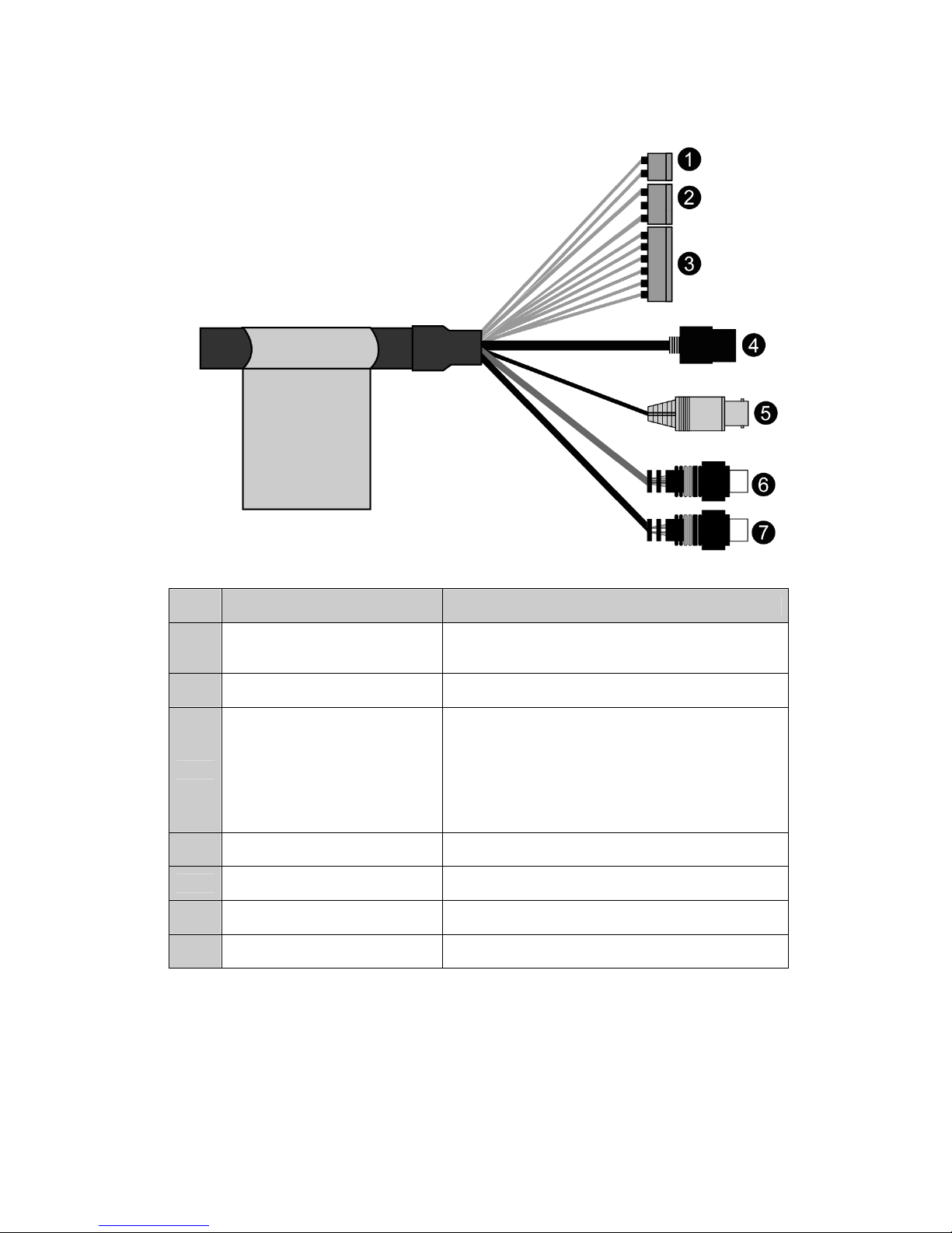
2.3 Basic Config ration of Dome Camera System
No.
Wire Color Description
1 Red: 12V DC+
White: 12V DC- Main Power: 2pin terminal
2 Pink, Brown Heater Power(Option): 3pin terminal
3
Black: GND
Gray: Alarm Input
Yellow: GND
Black&White: Alarm Output
Green: RS485+
Blue: RS485-
Alarm Input/Output, RS485: 6pin terminal
4 Black Ethernet: RJ45 Modular Jack
5 Yellow Video Composite Output: BNC Jack
6 Red Audio line output: RCA Jack
7 White Audio line input: RCA Jack
The dome camera must be installed by qualified service personnel in accordance with all local
and federal electrical and building codes.

7
2.4 Setting Dome Camera Address (ID)
To prevent damage, each dome camera must have a unique address (ID).
When installing multiple dome cameras using a multiple er, it is suggested that the dome camera
address match the multiple er port number.
The factory default setting is 1.
2.5 Connections
• Connecting to the RJ-45
Connect a standard RJ-45 cable to the network port of the dome camera. Generally a cross-over
cable is used for directly connection to PC, while a direct cable is used for connection to a hub.
• Connecting Alarms
AI (Alarm In)
You can use e ternal devices to signal the dome camera to react on events. Mechanical or
electrical switches can be wired to the AI (Alarm In) and G (Ground) connectors.
G (Gro nd)
NOTE: All the connectors marked G or GND are common.
Connect the ground side of the alarm input and/or alarm output to the G (Ground) connector.
AO (Alarm O tp t)
The dome camera can activate e ternal devices such as buzzers or lights. Connect the device to
the AO (Alarm Out) and G (Ground) connectors.
• Connecting to the RS485
The dome camera can be controlled remotely by an e ternal device or control system, such as a
control keyboard, using RS485 half-duple serial communications signals.
• Connecting Video o t connector
Connect the video out (BNC) connector to the monitor or video input.
• Connecting the Power
Connect the power of 12VDC 1.5A for the dome camera.
When using a 12VDC adapter, connector the positive(+) pole to the ‘+’ position and the
negative(-) pole to the ‘-‘ position.
Use satisfy clause 2.5 of IEC60950-1/UL60950-1 or Certified/Listed Class 2 power source only.

8
2.6 IP Assignment
When the dome camera, encoder or decoder is first connected to the network it has no IP
address. So, it is necessary to allocate an IP address to the device with the “SmartManager”
utility on the CD.
1. Connect the dome camera / device to the network and power up.
2. Start SmartManager utility (All programs > NautilusClient16 > SmartManager), the main
window will be displayed, after a short while any network devices connected to the network will
be displayed in the list.
3. Select the dome camera on the list and click right button of the mouse.
You can see the pop-up menu as below.
4. Select Assign IP Address. You can see Assign IP window. Enter the required IP address.
Note: For more information, refer to the SmartManager User’s Manual.

9
2.7 Getting Started
Once installed apply power to the dome camera. The dome camera will start a configuration
sequence.
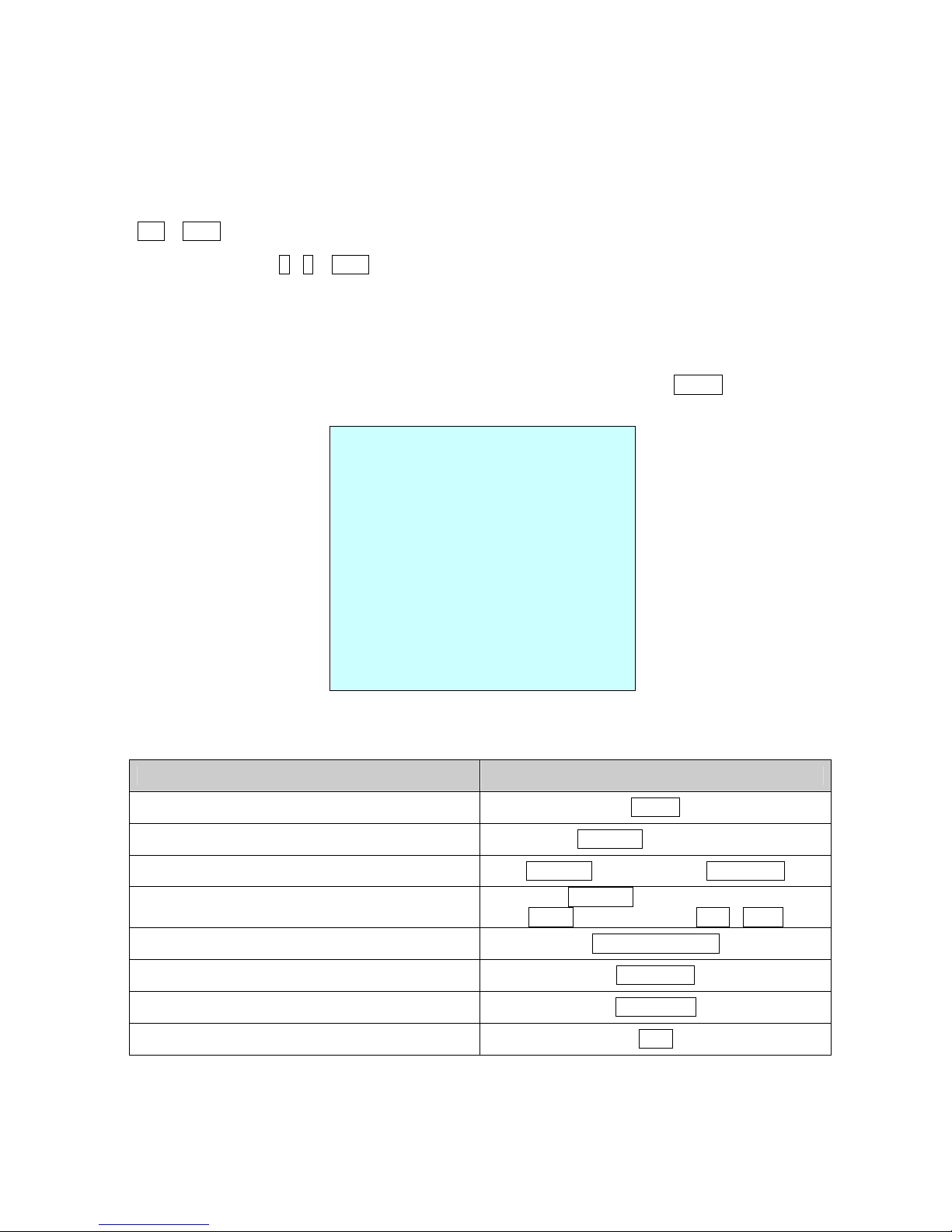
OSD Position
The dome can move the OSD position in the OSD position setup.
(AREA TITLE) (AF AE)
(FUNC TITLE )
(CTRL KEY TO MOVE)
SAVE AND EXIT(ESC TO CANCEL)
(DOME ID…)
(ANGLE…)
OSD Position Set p
001 AF AE
EMPTY DATA
DOMEID:0001
W→360 0,090 0
INFORMATION
DISPLAY
FUNCTION
UNDER RUNNING
CAMERA TITLE
CAMERA ID
VIEW DIRECTION
PAN & TILT ANGLE
PRESET TITLE
AREA TITLE
STATUS of
FOCUS and AE
10
Chapter 3 — Program and Operation
3.1 Dome Camera Selection
Before you program or operate a dome camera, you must select the dome camera by pressing
No. + CAM keys.
Example: Pressing 1 , 0 + CAM keys sequentially will select dome camera 10. The selected
dome camera ID will be displayed on the LCD monitor of the keyboard controller.
3.2 Accessing the On-Screen Men Utility
You can call up the On-screen menu utility on your monitor by pressing the MENU key on the
keyboard controller, the following On-screen menu utility will appear:
DOME MENU
AUTO SCAN
PRESET
TOUR
PATTERN
AREA TITLE
PRIVACY ZONE
CAMERA
DOME SETUP
DOME COMMUNICATION
FUNCTION RUN
EXIT(ESC TO EXIT)
3.3 How to control the On-Screen Men Utility
F nction B tton
Call the On-screen menu utility. MENU
Navigate through the menu items. Joystick p or down
Go into the sub-menu items. Joystick left or right or IRIS Open
Change value.
Enter the editing title mode.
Joystick left or right or
Zoom handle twist or Tele , Wide
Change value of angle. CTRL + Joystick
Enter the changing angle mode. IRIS Open
E it the changing angle mode. IRIS Close
Escape (EXIT) ESC
Table of contents
Other Eneo Security Camera manuals

Eneo
Eneo IPD-75M3610M0A User manual

Eneo
Eneo ICB-62M2713MAA User manual

Eneo
Eneo VK-1321/PIR User manual

Eneo
Eneo ENC-1001L User manual

Eneo
Eneo IEB-74M2812MAA User manual

Eneo
Eneo VKCD-1322 User manual

Eneo
Eneo IEB-54F0028M0A User manual

Eneo
Eneo TVD-2080V2812IR User manual

Eneo
Eneo DOME-WB8 User manual

Eneo
Eneo ICB-68M3611M0A User manual

Eneo
Eneo IPD-68M3611P5A User manual

Eneo
Eneo IPD-72A2712M5A User manual

Eneo
Eneo IED-64M2812MAA User manual

Eneo
Eneo IED-63F0037M0A User manual

Eneo
Eneo PXD-2030PTZ1080 User manual

Eneo
Eneo VKC-1338A/PIR User manual

Eneo
Eneo TPP-62A0012M0A User manual

Eneo
Eneo 227052 User manual

Eneo
Eneo ISM-52F0021WMA User manual

Eneo
Eneo PXB-2080MIR D User manual


