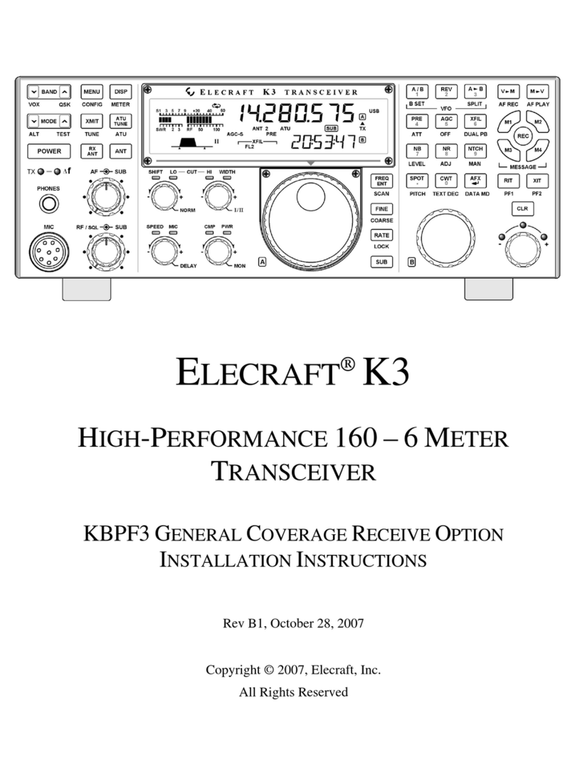
ELECRAFT K4 User manual

ELECRAFT K4 OPERATING MANUAL
Rev C9
Table of Contents
I. INTRODUCTION
USING THE BUILT-IN OPERATING MANUAL
K4 TRANSCEIVER OVERVIEW
INSTALLATION INSTRUCTIONS
REAR PANEL CONNECTIONS
II. FRONT PANEL REFERENCE
USING TAP, HOLD, and TOUCH CONTROLS
FRONT PANEL OVERVIEW
LEFT-SIDE CONTROLS
MULTI-FUNCTION CONTROLS
LCD SCREEN AND TOUCH CONTROLS
VFOs AND RIGHT-SIDE CONTROLS
III. OPERATING INSTRUCTIONS
PRIMARY FUNCTIONS

BAND SELECTION
ANTENNA SELECTION
OPERATING MODES
RECEIVER SETTINGS
TRANSMITTER SETTINGS
TX AND RX METERING
PANADAPTER
DUAL RECEIVE
HDR RECEIVE (K4HD)
AUDIO EFFECTS (AFX)
DIGITAL VOICE RECORDER (DVR)
USING THE STATUS DISPLAY
FREQUENCY MEMORIES
USING SPLIT
INTERNAL & EXTERNAL TRANSVERTERS
REMOTE CONTROL
MACRO PROGRAMMING
RTTY CONFIGURATION
FT8 / JT / ETC. CONFIGURATION
IV. MENU LISTING
V. TROUBLESHOOTING

_________________________________________________
I. INTRODUCTION
USING THE BUILT-IN OPERATING MANUAL
This operating manual is a compact reference to all K4 controls, connectors, display elements, and
menu entries. It also provides context-sensitive help during operation.
Please refer to the Elecraft K4 Owner's Manual for more detailed instructions on all topics. At
minimum, please read the fully illustrated short-form manual, Introduction to the Elecraft K4, to
become familiar with control and connector locations.
To view the built-in operating manual, tap the button labeled "?" at the lower left-hand corner of the
LCD screen:
For help with the most recent controls used, tap the LAST CTRL button one or more times.
To scroll through text, rotate the VFO A knob. Navigate by clicking on underlined links and using the
forward/backwards buttons. Tap the table of contents button to return to the top.
To search by topic, tap the magnifying glass button. If there's more than one match, the up/down
arrow buttons will navigate among them. Tap the magnifying glass button again to exit match
navigation and return to scrolling.
For a full-screen version of the operating manual, tap the resize button.

Key to Text Styles
Important cautions are shown in red.
The following text conventions are used when referring to controls:
[Physical Switch] <Touch Control> {Knob}
Switch, touch, and knob controls are shown in white for tap,yellow for hold, as on the transceiver
itself.
Many LCD labels, icons and graphics also function as touch controls. Those which appear in the form
of labeled switches are referred to as 'buttons' to differentiate them from physical switches.
MENU ENTRIES are shown as MENU:Name, e.g. MENU:LCD Brightness. For a full list of menu
entries, see IV. MENU LISTING.
** Indicates a feature that is still in development.
K4 TRANSCEIVER OVERVIEW
The K4 is a high-performance, direct-sampling software-defined radio (SDR). It covers the 160 ~ 6 m
bands, with continuous receive from 100 kHz ~ 54 MHz. 10 W and 100 W models are available. It can
be used with internal or external transverters to cover bands from VHF up.
Among the K4's notable features: A large color touch screen, as well as support for an external
monitor; extensive, easy to use controls; rich analog and digital connectivity; dual receive; built-in
data modes, and wide range antenna tuner. In addition to its extensive front panel controls, the K4
has full mouse support, and can also be controlled by an Elecraft K-Pod.
The K4's compact size and weight, combined with 11-15 VDC operation and low current drain, make
it suitable for field, travel, or home station use.
Since the K4 is an SDR, Elecraft can provide updates to its signal processing algorithms with

software changes rather than by adding new hardware. This ensures that the K4 can take advantage
of new modes, bands, or other features in the future. Since it uses direct sampling, signals are
digitized right at the receiver inputs, and the transmitter's amplifier chain is also driven by a digitized
signal. Older SDR architectures digitized signals at a low intermediate frequency (IF), resulting in
poor suppressions of down-conversion or up-conversion images.
There are three models: the basic K4, with one set of receive filters and one analog-to-digital
converter (ADC); the K4D, with a second set of receive filters and a second ADC; and the K4HD,
which adds a superheterodyne front end that can be enabled as needed to provide even greater
dynamic range. The superhet module uses high-performance, narrow-band crystal filters such as
those used in the Elecraft K3S.
Even the basic K4 provides simultaneous dual receive on the same or different bands/modes.
However, the K4D and K4HD models include an additional receiver module (KRX4) with a second set
of band-pass filters, improving signal handling during dual-receive operation on different bands. The
second receiver also permits diversity reception, i.e., the use of different antennas for the two
receivers to counteract fading (QSB).
A basic K4 can be upgraded to a K4D by installing the KRX4 option. Similarly, a K4D can be
upgraded to a K4HD by installing a KHDR4 module. Other internal options and external accessories
are applicable to all three models, including a wide-range ATU (KAT4), MH4 microphone, SP4
external speaker (1 or 2). For further information, visit www.elecraft.com.
INSTALLATION INSTRUCTIONS
CAUTION: Ground your K4 properly before operation using the provided wing nut ("GND"). For
suggestions, see www.arrl.org/grounding.
Even though the K4 has extensive internal protective circuitry, external protection against lightning
strikes is strongly recommended, especially in lightning-prone areas.

During storms and when the station is not in use for an extended period, disconnect ALL equipment
from the K4, including antennas, power supply, routers or hubs, and computers. Ethernet, USB, and
RS232 cables are a frequent source of damaging surge voltages.
Orientation and Air Flow
Provide at least 1" of free space both above and behind the transceiver. Ventilation holes on the
bottom and left sides must also not be blocked.
Using the Tilt Stand
If the K4 is placed on a desk or table, deployment of the tilt stand is strongly recommended to
facilitate easier interaction with the touch screen. This will also improve display viewing angle.
Removing LCD Protective Film
Carefully peel the protective film off the LCD. There's a small plastic tab at the upper right corner for
this purpose. If the film is left on, it will degrade the appearance of LCD graphics as well as touch
screen performance.
Power Supply
Use the shortest practical length of power cable, with heavy wire gauge to minimize voltage drop. The
supplied power cable includes fuses in both legs. The supplied cable is #12 AWG, and the fuses in
each leg are rated at 25 amps.
A power supply voltage of 13.8 to 14.2 V is preferred. For 100 W use, a 30 amp supply is
recommended. For 10 W use, a 5 amp supply will suffice. NOTE: If use of a switching supply results
in low-pitched repetitive noise or other artifacts when monitoring your K4's signal in another receiver,
consider using a well-regulated and filtered linear supply.
Minimum supply voltage is 11.0 V. The K4 will automatically reduce power output if the supply voltage
is too low to maintain good IMD performance at the selected RF output level.

Interfacing to Station Equipment
Refer to the REAR PANEL CONNECTIONS section, below, for descriptions of all connectors and
interfacing requirements. At minimum you'll need to connect a power supply, antenna, and station
ground.
Getting Started
Once your K4 is installed and you're ready to operate, you can get started in one of two ways: (1)
read the FRONT PANEL REFERENCE section to learn about each of the controls, or (2) jump to the
OPERATING INSTRUCTIONS section, which is more procedural in nature.
Software Updates
An internet connection is the preferred way to do software updates. To initiate an update, tap primary
function button <Fn>, then hold <UPDATE>. Once the software update screen is displayed, tap the
<?> button for detailed instructions on how to update software and read release notes.
REAR PANEL CONNECTIONS
Rear panel connections are briefly described below, from left to right and top to bottom as viewed
from the back. The information provided in this operating manual is limited; refer to the K4 owner's
manual for more details.
ANT 1, ANT 2, ANT 3
These are the HF/6 m transmit-receive antenna jacks. If an ATU is not installed, only the ANT 1 jack
will be present. Also see ANTENNA SELECTION.
ANT 4
Antenna jack for use with an internal transverter, if applicable. If no transverter is installed, the jack

will not be present.
12 VDC IN
Anderson Power Pole (APP) connectors for 11-15 V DC supply. 30 amp supply recommended for 100
W use. See INSTALLATION INSTRUCTIONS for cable and fusing requirements.
12 VDC OUT
12 V switched output for use with accessories, 1.5 amps max (protected by self-resetting fuse).
GROUND (Wing Nut)
For attachment of station ground. See INSTALLATION INSTRUCTIONS.
TX SMPL IN
If transmit IMD optimization** is enabled for use with an external linear amplifier (such as the Elecraft
KPA1500), connect its transmit output sample port to TX SMPL IN. Refer to the owner's manual for
signal level and calibration details.
Transmit IMD optimization can also be enabled for use with the K4's internal amplifier stages.
XVTR IF IN / RX ANT 2
This jack can be used as a general-purpose receive antenna, or for connection to an external
transverter (in conjunction with XVTR IF OUT). See TX AND RX ANTENNA SELECTION .
XVTR IF OUT
This can be used as the output drive signal for an external transverter.
RX ANT 1 IN
General-purpose receive antenna input. See ANTENNA SELECTION.

RX ANT OUT
When the RX ANT OUT jack is active, its signal can be used along with RX ANT 1 IN or XVTR IF
IN/RX ANT 2 IN to provide a path through an external band-pass filter, splitter, etc. The RX ANT OUT
signal is obtained from the transmit antenna path, so it passes through the ATU (if applicable) as well
as the transmit low-pass filters and T/R switch.
RX ANT OUT is only active if the main and sub receivers are both configured to use receive-only
antennas. See Using RX ANT OUT.
ETHERNET
Connect to station router or modem. Compatible with 10/100/1000 megabit rates. A high quality
shielded cable is strongly recommended; refer to Elecraft web site for available cable(s).
Ethernet connectivity is preferred for software updates and remote control applications, such as our
Virtual K4 program (see REMOTE CONTROL).
Note: If you have any difficulty with software updates, tap the "?" button from within the UPDATE
function. Also see TROUBLESHOOTING.
USB
The rear panel has two type A USB jacks and one of type B, labeled "PC". There is an additional type
A jack on the front panel. Any of the type A jacks may be used with a keyboard, mouse, memory
device, or Elecraft K-Pod. Wireless adapters may be used.
The type B USB jack provides two virtual COM ports, referred to in this manual as USB-PC1 and
USB-PC2, that can be used for radio control and soundcard I/O (digital version of LINE IN / LINE
OUT). LINE OUT is stereo; LINE IN is mono. Connect the cable to any USB-A jack on a host
computer or hub.
To set the baud rates for these ports, use the Serial USB-PCn: Baud Rate menu entries. Refer to
software application manuals for port setup instructions. (Plugging in new devices, including the K4,

may alter COM port assignments.)
To use the RTS and DTR signals of the USB-PCn ports for transmit functions (PTT, KEY, or FSK
select), or to configure them for Auto-Info frequency data output (AI), use the associated Serial
USB-PCn menu entries.
To set up these ports for soundcard receive audio, first tap the <MAIN RX> function button, then tap
<LINE OUT>. For soundcard transmit audio setup, tap <TX>, then <LINE IN>. Also see TX button
description.
A third COM port is also available for remote control/data; see RS-232, below.
VIDEO
Connection for an external monitor. The monitor can be configured to show only the panadapter,
which may be configured differently from the panadapter shown on the LCD. See Ext. Monitor
Function and LCD SCREEN AND TOUCH CONTROLS.
REF IN
A 10 MHz reference signal may be connected to this jack. The K4's internal reference oscillator will
lock to this signal when present. Also see ER100 (Error Messages).
LINE IN
This is an analog audio input (nominally 600 ohms) for connection to computers or other station
equipment that supply transmit audio to the K4. An example of this is a software application that
supplies data-mode audio signals, e.g. FT8, RTTY, or PSK31. In voice modes, LINE IN can be used
in lieu of, or in conjunction with, microphone audio; see TX button description.
Most computer software can alternatively provide LINE IN signals from a virtual COM port, eliminating
the need for analog cabling and potentially reducing noise. See description of rear-panel USB
connector, above.
Other manuals for K4
2
This manual suits for next models
2
Table of contents
Other ELECRAFT Transceiver manuals

ELECRAFT
ELECRAFT KX1 User manual

ELECRAFT
ELECRAFT K3 User manual

ELECRAFT
ELECRAFT KX3 User manual

ELECRAFT
ELECRAFT K3 User manual

ELECRAFT
ELECRAFT K3S User manual

ELECRAFT
ELECRAFT K2 SSB User manual

ELECRAFT
ELECRAFT KX3 User manual

ELECRAFT
ELECRAFT K2 User manual

ELECRAFT
ELECRAFT K2 User manual

ELECRAFT
ELECRAFT K3 User manual

ELECRAFT
ELECRAFT KNB2 User manual

ELECRAFT
ELECRAFT K3 User manual

ELECRAFT
ELECRAFT KRX3 Owner's manual

ELECRAFT
ELECRAFT K3S User manual

ELECRAFT
ELECRAFT KX2 User manual

ELECRAFT
ELECRAFT P3 User manual

ELECRAFT
ELECRAFT KH1 User manual

ELECRAFT
ELECRAFT K3 User manual

ELECRAFT
ELECRAFT K3 User manual

ELECRAFT
ELECRAFT K4 Reference manual