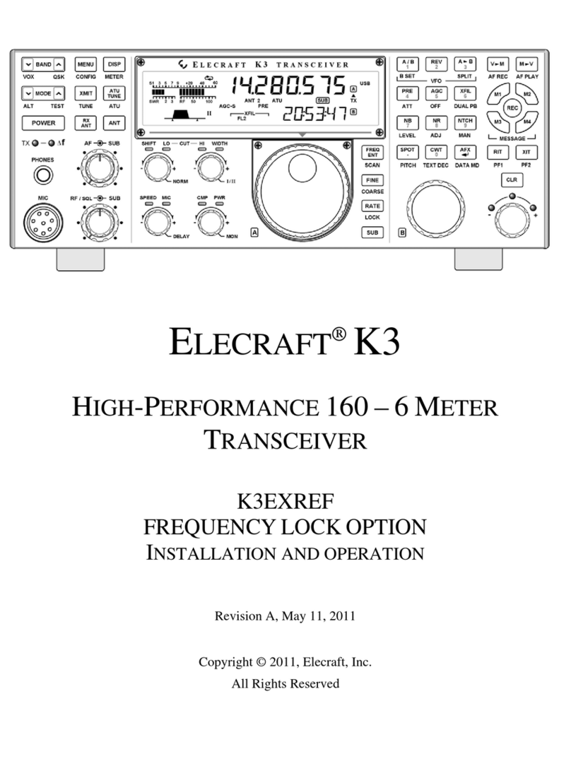
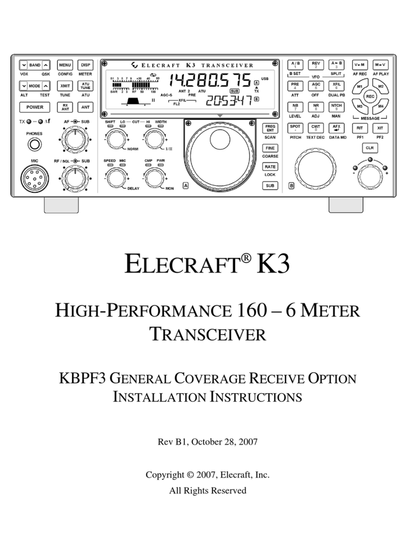
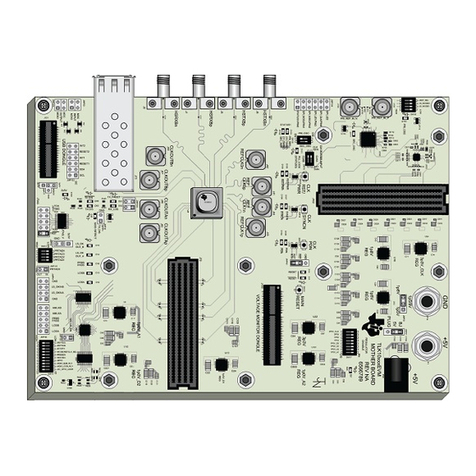
ELECRAFT K3S User manual

ELECRAFT K3S
HIGH-PERFORMANCE
160 – 6 METER TRANSCEIVER
KBPF3A GENERAL COVERAGE RECEIVE OPTION
INSTALLATION INSTRUCTIONS
Rev A1, July 2, 2015
Copyright © 2015, Elecraft, Inc.
All Rights Reserved
E740265

2
Contents
Introduction ............................................................................................................................................... 3
Customer Service and Support ............................................................................................................................ 3
Technical Assistance ....................................................................................................................................... 3
Repair / Alignment Service ............................................................................................................................. 3
Preventing Electrostatic Discharge Damage ............................................................................................ 4
Choosing an Anti-Static Mat ............................................................................................................................... 5
Preparing for Installation .......................................................................................................................... 5
Tools Required .................................................................................................................................................... 5
Parts Included ...................................................................................................................................................... 6
Installation Procedure ............................................................................................................................... 6
Removing the Top Cover and Chassis Stiffener ................................................................................................. 6
Removing the K144XV 2-Meter Module ........................................................................................................... 7
Removing the KRX3 or KRX3A Sub Receiver Module .................................................................................... 8
Installing the KBPF3A in the Sub Receiver ........................................................................................................ 9
Installing Standoffs on the Sub Receiver Board ........................................................................................... 10
Installing the KBPF3A on the Sub Receiver Board ...................................................................................... 11
Installing the KBPF3A in the Main Receiver ................................................................................................... 12
Installing the Standoffs on the RF Board ...................................................................................................... 12
Installing the KBPF3A Board on the RF Board ............................................................................................ 14
Reassembly ....................................................................................................................................................... 15
Enable the KBPF3A Module............................................................................................................................. 16
Appendix A Modification Required for K3 and KRX3 Receivers ........................................................ 17
Parts Required ................................................................................................................................................... 17
Tools Required .................................................................................................................................................. 17
Installation in the KRX3 Sub Receiver ............................................................................................................. 18
Installation in the K3 Main Receiver ................................................................................................................ 19
Appendix B Checking Synthesizer Type in K3 Transceivers ............................................................... 22
Elecraft manuals with color images may be downloaded from
www.elecraft.com.

3
Introduction
This manual covers the installation of the KBPF3A General Coverage Receive option in your K3S or K3
transceiver.
The KBPF3A provides the proper input filters to optimize receiver sensitivity outside of the Ham bands from
100 KHz to 30 MHz and from 48 MHz through 54 MHz. Both the main receiver and the optional KRX3A sub
receiver may be equipped with the KBPF3A.
The KBPF3A consists of a single circuit board supported by two threaded standoffs. It plugs into the K3S or K3
RF board that covers the bottom of the chassis enclosure, or the KRX3A Subreceiver board inside the shielded
enclosure. The attachment points for the KBPF3A and KBPF3 are identical, so no change is needed if you are
upgrading from the KBPF3 to the KBPF3A.The K3S and later K3 transceivers are already equipped with the
necessary standoffs in both the KRX3A sub receiver and the main receiver. For those with an older K3 that does
not have the necessary standoffs pre-installed, a pair of standoffs and all the necessary hardware is included in
this kit, along with full instructions for installing them.
In any case, only a few simple hand tools are needed and the installation of the KBPF3A board does not involve
any soldering. The tools required are listed on page 5.
If you are adding the KBPF3A to s K3 transceiver:
1. The K3 must be equipped with the KSYN3A synthesizer to tune below 500 kHz. The
KSYN3A synthesizer is standard on the K3S and newer K3 transceivers. See
Appendix B on page 22 if you aren't sure what type of synthesizer is installed in
your K3.
2. K3 transceivers need a bypass capacitor added to the K3 RF board if the KBPF3 is
being added to the main receiver or. A bypass capacitor must be added to the KRX3
main board if the KBPF3 is being added to the sub receiver. See Appendix A on
page 17 for detailed instructions for installing the capacitor(s).
Customer Service and Support
Technical Assistance
You can send e-mail to [email protected] and we will respond quickly - typically the same day Monday
through Friday. Telephone assistance is available from 9 A.M. to 5 P.M. Pacific time (weekdays only) at 831-
662-8345. Please use e-mail rather than calling when possible since this gives us a written record of the details
of your problem and allows us to handle a larger number of requests each day.
Repair / Alignment Service (We want to make sure everyone succeeds!)
If necessary, you may return your Elecraft product to us for repair or alignment. (Note: We offer unlimited email
and phone support to get your kit running, so please try that route first as we can usually help you find the
problem quickly.)
IMPORTANT: You must contact Elecraft before mailing your product to obtain authorization for the
return, what address to ship it to and current information on repair fees and turn around times. (Frequently we
can determine the cause of your problem and save you the trouble of shipping it back to us.) Our repair location
is different from our factory location in Aptos. We will give you the address to ship your kit to at the time of
repair authorization. Packages shipped to Aptos without authorization will incur an additional shipping charge
for reshipment from Aptos to our repair depot.

4
Preventing Electrostatic Discharge Damage
Sensitive components may be damaged by Electrostatic Discharge (ESD) simply by touching them or a circuit
board containing them unless you take specific steps to prevent such damage. Damage may occur with static
discharges far too little for you to notice.
A damaged component may not fail completely at first. Instead, the damage may result in below-normal
performance for an extended period of time before you experience a total failure.
Parts which are especially ESD-sensitive are identified in the parts list and in the assembly procedures.
We strongly recommend you take the following anti-static precautions (listed in order of importance) to ensure
there is no voltage difference between the components and any object that touches them:
Leave ESD-sensitive parts in their anti-static packaging until you install them. The packaging may be a
special plastic bag that allow static charges to flow harmlessly over their surface, or a component’s
leads may be inserted in conductive foam that keep them at the same potential.
Wear a conductive wrist strap with a series 1-megohm resistor that will constantly drain off any static
charge that accumulates on your body. If you do not have a wrist strap, touch a ground briefly before
touching any sensitive parts to discharge your body. Do this frequently while you are working. You can
collect a destructive static charge on your body just sitting at the work bench.
Elecraft's 1-Year Limited Warranty
This warranty is effective as of the date of first consumer purchase (or if shipped from factory, date product is shipped
to customer). It covers both our kits and fully assembled products. For kits, before requesting warranty service, you
should fully complete the assembly, carefully following all instructions in the manual.
Who is covered: This warranty covers the original owner of the Elecraft product as disclosed to Elecraft at the time of
order. Elecraft products transferred by the purchaser to a third party, either by sale, gift or other method, who is not
disclosed to Elecraft at the time of original order, are not covered by this warranty. If the Elecraft product is being
bought indirectly for a third party, the third party's name and address must be provided to Elecraft at time of order to
insure warranty coverage.
What is covered: During the first year after date of purchase, Elecraft will replace defective or missing parts free of
charge (post-paid). We will also correct any malfunction to kits or assembled units caused by defective parts and
materials. Purchaser pays inbound shipping to Elecraft for warranty repair, Elecraft will pay shipping to return the
repaired equipment to you by UPS ground service or equivalent to the continental USA and Canada. Alaska, Hawaii
and outside U.S. and Canada actual return shipping cost paid by owner.
What is not covered: This warranty does not cover correction of kit assembly errors. It also does not cover
misalignment; repair of damage caused by misuse, negligence, or builder modifications; or any performance
malfunctions involving non-Elecraft accessory equipment. The use of acid-core solder, water-soluble flux solder, or any
corrosive or conductive flux or solvent will void this warranty in its entirety. Also not covered is reimbursement for loss
of use, inconvenience, customer assembly or alignment time, or cost of unauthorized service.
Limitation of incidental or consequential damages: This warranty does not extend to non-Elecraft equipment or
components used in conjunction with our products. Any such repair or replacement is the responsibility of the customer.
Elecraft will not be liable for any special, indirect, incidental or consequential damages, including but not limited to any
loss of business or profits.

5
WARNING
DO NOT attach a ground directly to yourself without a current-limiting resistor as this poses a
serious shock hazard. A wrist strap must include a 1-megohm resistor to limit the current flow. If
you choose to touch an unpainted, metal ground to discharge yourself, do it only when you are
not touching live circuits with any part of your body.
Use a grounded anti-static mat on your work bench (see below).
If you pick up a pc board that was not placed on an anti-static mat or in an anti-static package, touch
first a ground plane connection on the board such as a connector shell or mounting point.
If you use a soldering iron to work on a circuit board, be sure your iron has an ESD-safe grounded tip
tied to the same common ground used by your mat and wrist strap.
Choosing an Anti-Static Mat
An anti-static mat must bleed off any charge that comes in contact with it at a rate slow enough to avoid a shock
or short circuit hazard but fast enough to ensure dangerous charges cannot accumulate. Typically, a mat will
have a resistance of up to 1 Gigaohm (109 ohms). Testing a mat requires specialized equipment, so we
recommend that you choose an anti-static mat that comes with published resistance specifications and clean it as
recommended by the manufacturer. Testing has shown that many inexpensive mats that do not specify their
resistance have resistance values much too high to provide adequate protection, even after they were cleaned
and treated with special anti-static mat solutions.
Suitable anti-static table mats are available from many sources including:
U-line (Model 12743 specified at 107 ohms)
Desco (Model 66164, specified at 106 to 108 ohms)
3MTM Portable Service Kit (Model 8505 or 8507, specified at 106 to 109 ohms)
Preparing for Installation
Tools Required
1. #0 and #1 size Phillips screwdrivers. To avoid damaging screws and nuts, a power screwdriver is not
recommended. Use the screwdriver that best fits the screw in each step.
2. Small needle-nose pliers or tweezers to position small parts.
3. Soft cloth or clean, soft static dissipating pad to lay cabinet panels on to avoid scratching.
The following tools are strongly recommended:
1. ESD wrist strap.
2. Static dissipating work pad.

6
Parts Included
The following parts should be included in your kit. Check to ensure you have them all. If any parts are damaged
or missing, contact Elecraft for replacements (see Customer Service and Support, page 3).
ILLUSTRATION DESCRIPTION QTY. ELECRAFT
PART NO.
KBPF3A Printed Circuit Board
ESD Sensitive. Follow ESD safe handling
procedures. Keep in ESD-safe bag until
installed.
1 E850269
Standoff, 4-40, 1/2” (13 mm) 2 E700061
Screw, 4-40, 1/4” (6.4 mm) 4 E700005
Lock Washer, #4 split 6 E700004
Installation Procedure
As you install components and reassemble your K3S or K3, be sure all the screws are in
place and secure, but do not over tighten them. Failure to tighten all screws may result in
poor shielding of sensitive components, resulting in possible noise or birdies in the receiver
as well as other difficult-to-trace problems.
Removing the Top Cover and Chassis Stiffener
Disconnect power and all cables from your K3S/K3.
Remove the nine screws to free the top cover as shown in Figure 1. After the cover is open, lift it gently to
reach the speaker wire connector. Unplug the speaker then set the top cover aside in a safe place.
Whenever you remove screws from a panel, if one screw seems too tight to loosen
without damaging it, first loosen the other screws then try again. Sometimes one screw
binds in its hole when the other screws are tightened.

7
Figure 1. Removing K3S/K3 Top Cover.
CAUTION: Touch an unpainted metal ground or wear a grounded wrist strap
before touching components or circuit boards inside the K3S/K3. See Preventing
Electrostatic Discharge Damage on page 4 for more information.
Remove the stiffener bar that runs from side to side across the top of the chassis. This is the bar the three
screws across the center of the top cover thread into. The bar is held in place by a single screw at each side and,
if the KPA3A 100 watt option is installed, by two screws attaching it to the KPA3A shield. KPA3A and some
older KPA3 shields have PEM nuts permanently attached to the shield for the screws. Others use ordinary nuts
that must be removed with the screws and lock washers.
Removing the K144XV 2-Meter Module
If you do not have the K144XV 2-meter option installed, skip this section and go to Removing the KRX3 or
KRX3A Sub Receiver Module on page 8.
The K144XV module is mounted on the left side panel of the K3. Remove the five screws shown in
Figure 2 and lift the top cover off of the module. Note: Some units may have a sixth screw in the hole near the
Elecraft name on the top cover that must be removed.
Figure 2. Removing the K144XV 2 Meter Module.
Unplug the coaxial cables and the power connector attached to the K144XV module. Pull on the metal part
of the TMP coaxial connectors (see Figure 4) . Do not pull on the cables.

8
Remove the three 6-32 screws that secure the K144XV module to the side panel. Hold the module to keep
it from falling if the KRX3 sub receiver is not installed. Lift the module out, set the top cover on it to protect it,
and set it aside in a safe place.
Removing the KRX3 or KRX3A Sub Receiver Module
If your K3S or K3 is equipped with the optional KRX3 or KRX3A sub receiver, you must remove the sub
receiver module to install the KBPF3A in either the main receiver or the sub receiver. The sub receiver module
is the “L” shaped metal enclosure (see Figure 3). Remove the sub receiver module as follows:
Remove the two 1-1/2” (38 mm) screws and lock washers shown in Figure 3. These screws extend all the
way through the KRX3 module and secure it to standoffs mounted on the main RF board that fills the bottom of
the K3S/K3.
Figure 3. Removing the KRX3 or KRX3A Module.
In the following steps you will handle small TMP coaxial connectors. These are friction-
fit connectors shown in Figure 4. Handle the connectors by the grips as shown. Do not pull
on the coaxial cable.
Figure 4. TMP Coaxial Connectors.

9
Hold the KRX3 or KRX3Asubreceiver module by the two brass knurled nuts on the top, and lift it straight
up to gain access to the small TMP coaxial connectors plugged into the sub receiver module. There are two
along the front. There may be one at the back as well, depending upon the options installed. As you lift the sub
receiver module, it will unplug from two small interface circuit boards. One is at the front and the other is at the
rear. These small boards may come out with the module or they may remain attached to the main RF board.
Unplug the TMP coaxial cables leading to the sub receiver module, then lift the module free and set it aside.
Locate the two small interface circuit boards that fit between the connectors on the KRX3 module and the
connectors on the RF board. Remove them and put them in a safe place.
Installing the KBPF3A in the Sub Receiver
If you are not installing a KBPF3A in the sub receiver, go directly to Installing the KBPF3A in the Main
Receiver on page 12.
Unscrew the two knurled nuts shown in Figure 5 and lift the top half of the enclosure off. There are two
unthreaded sleeves over the long screws above the circuit board that will slide off easily (see Figure 6). Be sure
you don’t lose them.
Figure 5. Removing the Top of the Sub Receiver Enclosure.

10
Check to see if the standoffs are already mounted on the sub receiver at the locations shown in Figure 6. if
so, go directly to Installing the KBPF3A on the Sub Receiver Board on page 11 Otherwise continue with
Installing Standoffs on the Sub Receiver Board below.
Figure 6. Sub Receiver PC Board
Installing Standoffs on the Sub Receiver Board
Remove the two unthreaded sleeves over the long screws shown in Figure 6, then remove the two PC board
mounting screws. Each screw has a split lock washer under it.
Lift the pc board with the two pony boards and filters attached out of the bottom half of the enclosure. The
board fits snugly in the bottom of the enclosure with small bumps along the edges of the board resting in small
holes along the sides of the enclosure. Lift the board straight up and off of the long screws.
Install the 1/2” (13 mm) standoffs at locations E1 and E3 on the sub receiver pc board (see Figure 6). Use
the hardware exactly as shown in Figure 7. The lock washer between the standoff and the pc board is very
important to establish the correct height above the board.
Figure 7. Installing the Standoffs.
Other manuals for K3S
6
Table of contents
Other ELECRAFT Transceiver manuals

ELECRAFT
ELECRAFT KNB2 User manual

ELECRAFT
ELECRAFT KBPF3 User manual

ELECRAFT
ELECRAFT K3 User manual

ELECRAFT
ELECRAFT K4 Reference manual

ELECRAFT
ELECRAFT K3 User manual

ELECRAFT
ELECRAFT K3 User manual

ELECRAFT
ELECRAFT KPA3 User manual

ELECRAFT
ELECRAFT K2 User manual

ELECRAFT
ELECRAFT K2 Reference guide

ELECRAFT
ELECRAFT KX3-2M Supplement

ELECRAFT
ELECRAFT K2/100 User manual

ELECRAFT
ELECRAFT K3 User manual

ELECRAFT
ELECRAFT P3 User manual

ELECRAFT
ELECRAFT K3 User manual

ELECRAFT
ELECRAFT K2 User manual

ELECRAFT
ELECRAFT K144XV Owner's manual

ELECRAFT
ELECRAFT XV50 User manual

ELECRAFT
ELECRAFT K3S User manual

ELECRAFT
ELECRAFT KX3 Operating instructions

ELECRAFT
ELECRAFT K2 User manual