East R/C SLEDG User manual
Instruction Manual
Wing Span: 48"
Weight: 22 oz. +/-
Wing Area: 552 Sq. In.
Motor: 200+ Watt Brushless Outrunner (i.e. Hang-It R/C X2217/08)
Radio Gear: 4 Channel minimum, 4 mini servos
Designed by East R/C's Chris Hockaday
Distributed exclusively by East R/C
Wing Loading: 5.8 oz/Sq. ft.

Page: 1
Thank you for your patronage to East R/C! Your support of our products is tremendously
appreciated. We are a family owned and operated company and are avid R/C modelers,
just like you. By purchasing our products you enable us to produce more products for our
modeling friends across the globe. Thank you!
The SLEDG is designed to be a lightweight 3D foamy, capable of any 3D maneuver in the
book while feeling much lighter on the stick than that of a traditional foamy airplane.
Build time should be around 2 hours and we have included a Landing Gear option, should
you choose to use it. The hardware package is of only the best quality available to us and
we have left no stone unturned. Everything you need, less power plant and radio system,
is included. So, get to building and please, let us know what you think. Your feedback
helps us to better improve upon our products.
Thanks again!
East R/C

Page: 2
Table of Contents
• Introduction Page 1 -
• Table of Contents Page 2 -
• Kit Contents Page 3 -
• Required Equipment Page 4 -
• Required Additional Hardware Page 4 -
• Recommended Tools and Supplies Page 4 -
• Painting Foam Page 5 -
• Assembly Guide Page 6 -
o Wing Panels Page 6 Steps 1-18
o Horizontal Fuse Section Page 9 Steps 19-22
o Fuselage Page 9 Steps 23-38
o Attaching Wing to Fuselage Page 12 Step 39-42
o Beveling & Hinging the Control Surfaces Page 13 Steps 43-49
o Installing the Firewall Page 15 Steps 50-55
o Installing the Control Horns Page 16 Steps 56-62
o Making & Installing Rudder & Elevator Pushrods Page 17 Steps 63-67
o Servo Installation Page 18 Steps 68-72
o Landing Gear Installation Page 19 Steps 73-83
o Carbon Fiber Trussing Reinforcements Page 21 Steps 84-85
o Mounting the Motor Page 21 Steps 86-87
o CG Page 22 Step 88
o Radio & Throw info Page 22 Step 88
• User Notes Page 22 -
Page: 3
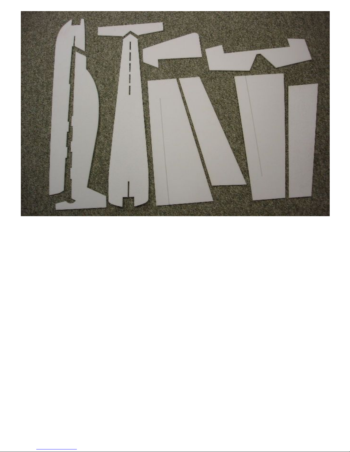
Kit Contents:
1. Horizontal Fuse Section
2. Horizontal Stabilizer
3. Top Fuse Section
4. Bottom Fuse Section
5. Left & Right Wing Panels
6. Left & Right Ailerons
7. Elevator
8. Rudder
1
2
4
3
6
5
6
7
8
5
Hardware Included:
1 Carbon Fiber Strip Leading Edge (39.5")
1 Carbon Fiber Strip Leading Edge Scab Piece (8.5")
2 Carbon Fiber Strip Trailing Edge Pieces (24.25")
1 Carbon Fiber Rod Spar (40")
3 Carbon Fiber Rod Truss Reinforcements (40")
2 Carbon Fiber Tubes (Rud/Elev Pushrod Mid Sections)
2 Straight Linkage Wires (Rud/Elev)
4 "L" Bend Linkage Wires (Ail/Rud/Elev)
4 "L" Bend Clips/Keepers
4 EZ Connectors (Servo Side Linkage Wire Keepers)
4 Razor Control Horns
2 Wheels
1 Tail Skid
2 Wheel Collars
2 Pieces of Landing Gear Wire (un-bent)
2 Carbon Fiber Square Tube Landing Gear Blocks
2 Light Ply Landing Gear Side Plates
2 Landing Gear Side Plate Support Pegs
1 Landing Gear Retainer Band
1 Light Ply Firewall
1 6" Strip of Hook & Loop for RX/Batt/ESC placement
1 Roll of 3M Blenderm for Surface Hinging

Page: 4
Required Equipment (not included):
• Motor:
o Hang-It R/C X2217/08, Hang-It R/C X20 Amp ESC, PolyQuest 1500mah 3s
o APC 11x4.7 Slow Flyer Prop
• Radio:
o 4-channel TX/RX recommended.
o Four (4) servos:
§
Four (4) mini servos for surfaces (i.e. Hitec HS-82MG's)
§
HS-65 Can be used, but they can be stripped in hard maneuvers
Recommended Tools and Supplies (not included):
• 5 minute epoxy or Hot Glue for Firewall
• Foam Safe Super Glue (CA..i.e. Mercury M100F)
• Foam Safe Activator (i.e. Mercury MMH16)
• Hobby Knife
• Extra NEW #11 Blades
• Pen Vise w/ Drill Bits
• Straight Edge
• Miscellaneous Screw Drivers and metric allen keys/hex drivers
• Foam Safe Spray Paint (Optional)
3/16" Drill Bit and drill
•

Page: 5
Painting Foam:
If you want to paint your SLEDG, it is usually best to dress it up before assembly of the
kit. Be mindful of the paint you intend to use. Most spray paints are not foam safe and if
you use the wrong paints, your foam will transform from a solid to a liquid in relatively
short period of time. There are several paints available that are foam safe. Here are a few:
1. Testors Model Car Spray Paint
2. Tamiya Model Car Spray Paint
3. Krylon Short Cuts
4. Foam Spray Paint from your local arts & crafts store
5. Most airbrushed acrylics
You can create masks from thin posterboard and other materials that will allow you to
create cool effects. If you are interested in learning more about techniques for painting
foam airplanes, go to this thread at FlyingGiants.com:
http://www.flyinggiants.com/forums/fg6/25009-awesome-foamy-schemes.html
Page: 6
p
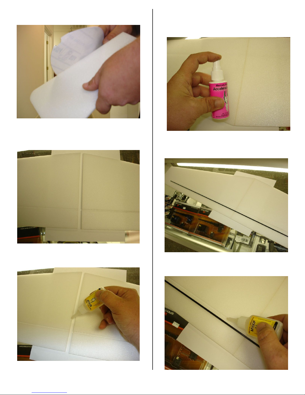
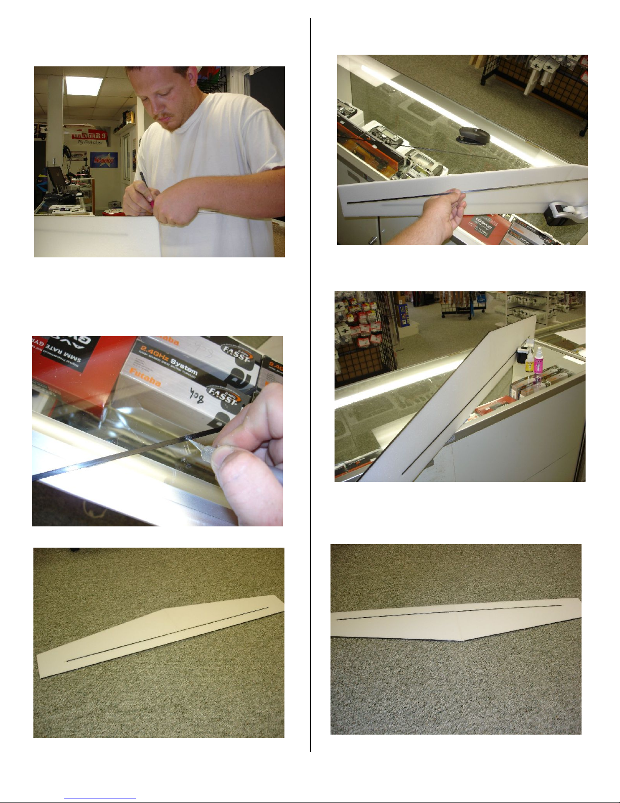
1. Lightly sand all of the foam parts edges
before assembly.
p
2. Locate the left & right wing panels and
use a piece of wax paper underneath to
catch any excess glue.
p
3. Apply a bead of foam safe glue down the
mating side of the wing panels.
p
4. Pull them together, aligning the the
pre-cut wing spar groove, and spray with
foam safe accelerator.
p
5. Locate and test fit the Carbon Fiber
Wing
Spar into the wing.
p
6. Run a bead of foam safe glue down the
length of the groove press in the spar & spray
with foam safe accelerator.
Page: 7
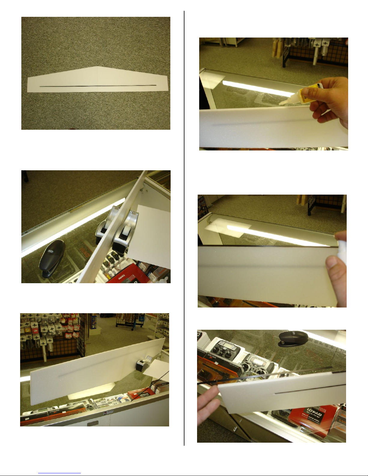
p
7. Spar installed.
p
8. If you don't have someone to help you,
use 2 weighted objects to hold the wing
while installing the leading and trailing edge
carbon fiber strips.
p
9. Locate the full length carbon fiber strip
and prepare to apply it to the leading edge.
p
10. Mark a line on the leading edge at 8.5"
and glue from that point down to the
opposite wingtip.
p
11. Place the carbon fiber strip on the
leading edge, starting at the mark,
running the length to the opposite wing
tip, then spray with accelerator.
p
12. If the scab piece is too long, mark it
with a pencil as shown.
Page: 8
p
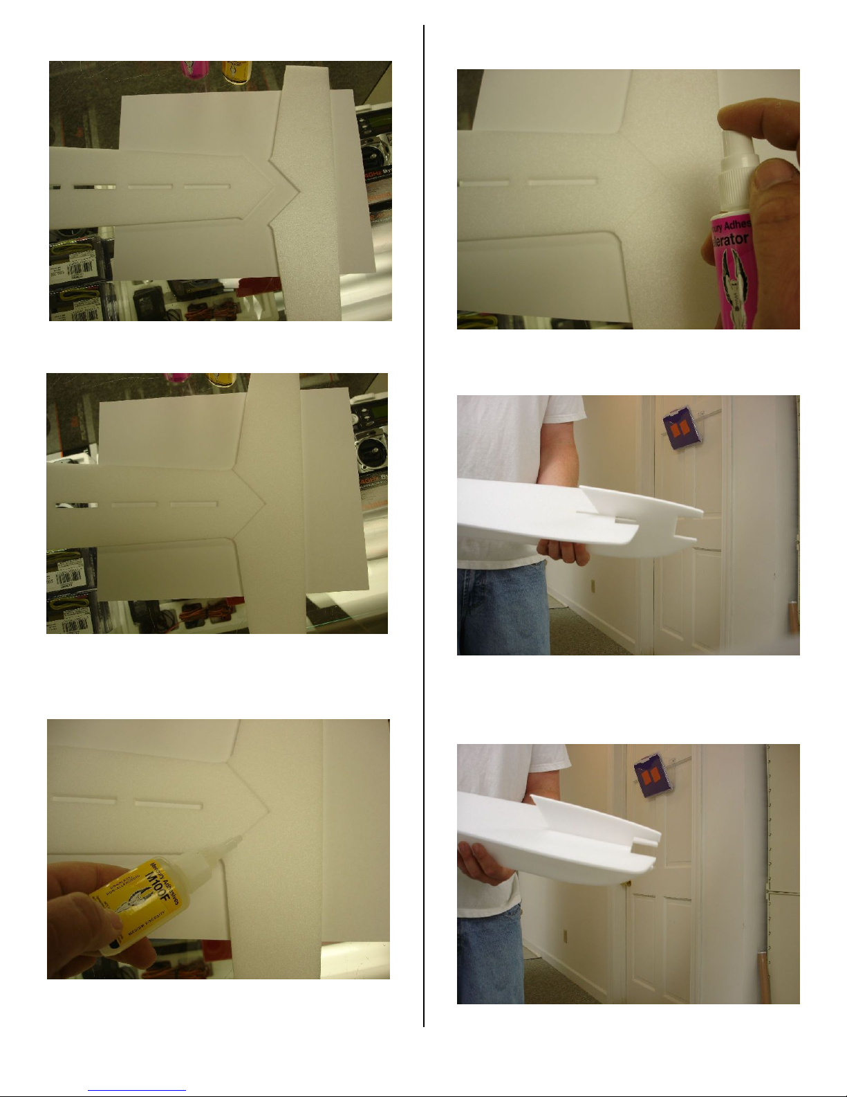
13. If you do not have a pencil, you can
score a mark with your hobby knife.
p
14. Cut the trip to your marked length
with a back and forth, sawing motion. Glue
The piece to the remainder of the leading
edge.
p
15. Leading Edge Complete:
p
16. Flip the wing over, leading edge down, &
Glue the trailing edge strips on..
p
17. Trim tips if necessary to remove any
over hang.
18. Trailing Edge Complete:
p
Page: 9
p
19. Prepare the Horizontal Stab &
Horizontal fuse sections for gluing.
p
20. Check the fit to make sure the stab is
not upside down before gluing.
p
21. Run a bead of foam safe glue onto
each surface.
p
22. Hold the pieces firmly together and spray
with accelerator.
p
23. Slide the bottom fuse section onto the
horizontal fuse section, starting at the nose.
p
24. Make sure the firewall area is
aligned properly.
Table of contents


