Denver 359/2807 User manual
MADE IN
BRITAIN
Assembly Instructions - Please keep for future reference
If you need help or have damaged or missing parts, call the Customer Helpline: 03456 400800
Issue 3 - 16/01/15
Important - Please read these instructions fully before starting assembly
ALR3095
359/2807
362/8685
333/6908
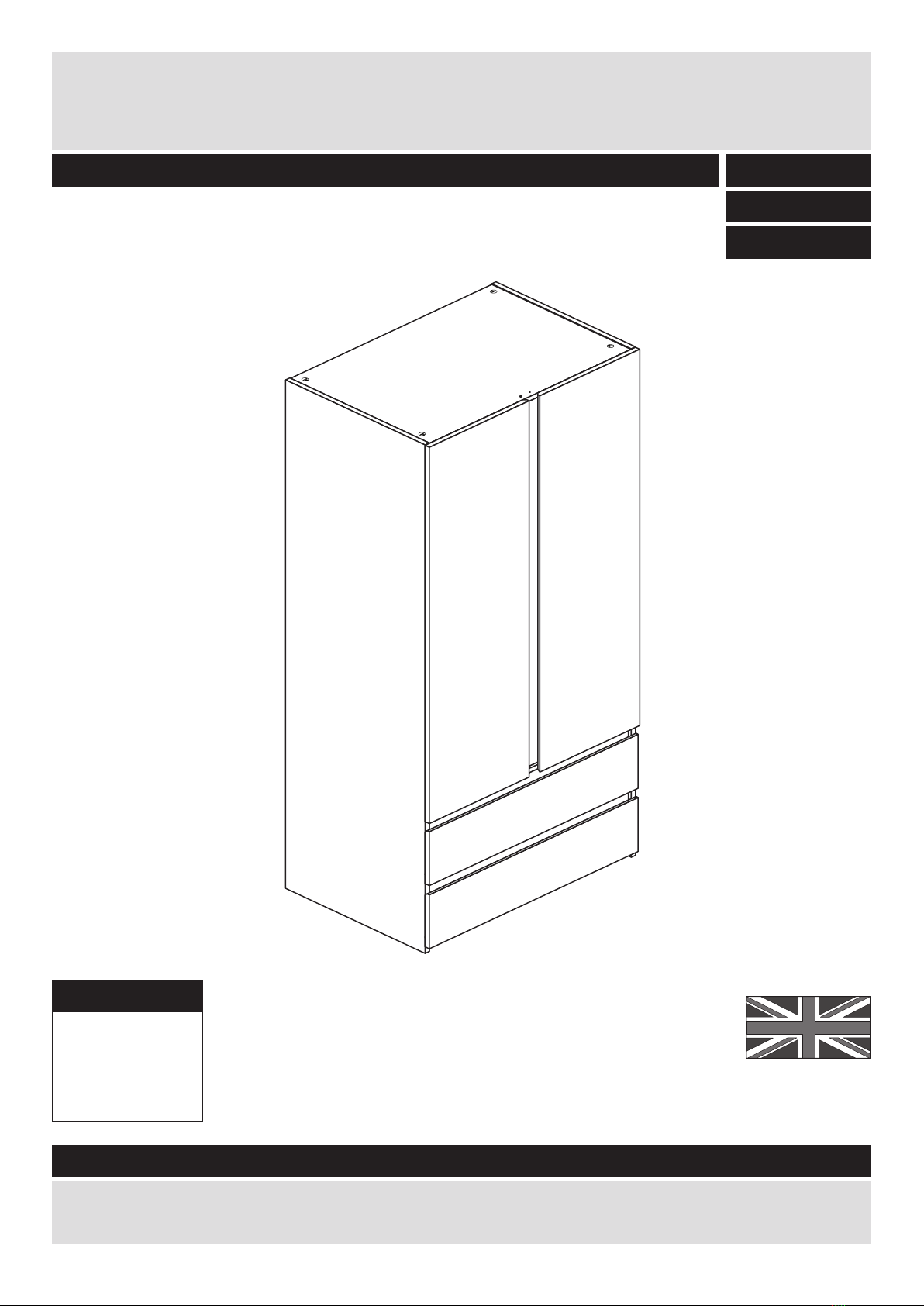
Denver - 2 Drawer 2 Door Robe
Dimensions
Width - 75cm
Depth - 50cm
Height - 181cm
Issue 2 - 08/01/15 - Depth of the Top/Base panels reduced to 494mm.
Issue 3 - 16/01/15 - Length of Hanging Rail changed to 710mm
Updated helpline number.
Safety and Care Advice
Important - Please read these instructions fully before starting assembly
• Warning: This unit weighs
approximately 52kgs.
Please lift with care.
• Check you have all the
components and tools listed on
pages 1, 2 and 3.
• Remove all fittings from the
plastic bags and separate them
into their groups.
• Keep children and animals
away from the work area, small
parts could choke if swallowed.
• Parts of the assembly will be
easier with 2 people.
• Make sure you have enough
space to layout the parts before
starting.
• Do not stand or put weight on
the product, this could cause
damage.
• Assemble the item as close to
its final position (in the same
room) as possible.
• Assemble on a soft level
surface to avoid damaging the
unit or your floor (use opened
out unit carton).
1
Care and maintenance
• Only clean using a damp cloth
and mild detergent, do no use
bleach or abrasive cleaners.
• From time to time check that
there are no loose screws on
this unit.
• This product should not be
discarded with household
waste. Take to your local
authority waste disposal centre.
Note: If required the next page
can be cut out and used as
reference throughout the
assembly. Keep this page with
these instructions for future
reference.
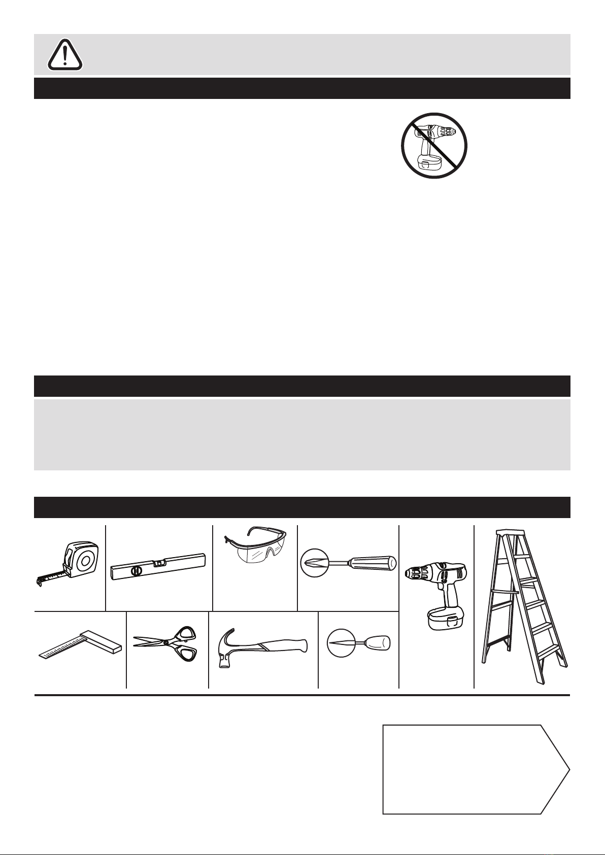
Tools required
Rule
Scissors
Spirit
level
Hammer Bradawl
Eye protection
(when using a
hammer or drill)
Cross-head
screwdriver
Step
ladder
Electric drill
(only use
when drilling
into walls)
Square
mm 10 20 30 40 50 60 70 80 90 100
mm 10 20 30 40 50 60 70 80 90 100
• We do not
recommend the
use of power
drill/drivers for
inserting screws,
as this could damage the unit.
Only use hand screwdrivers.
• Safety note: It is
recommended that this unit is
secured to a wall using the
overbalance protector kit
supplied or, an alternative fixing
method of your choice.
• Dispose of all packaging
carefully and responsibly.
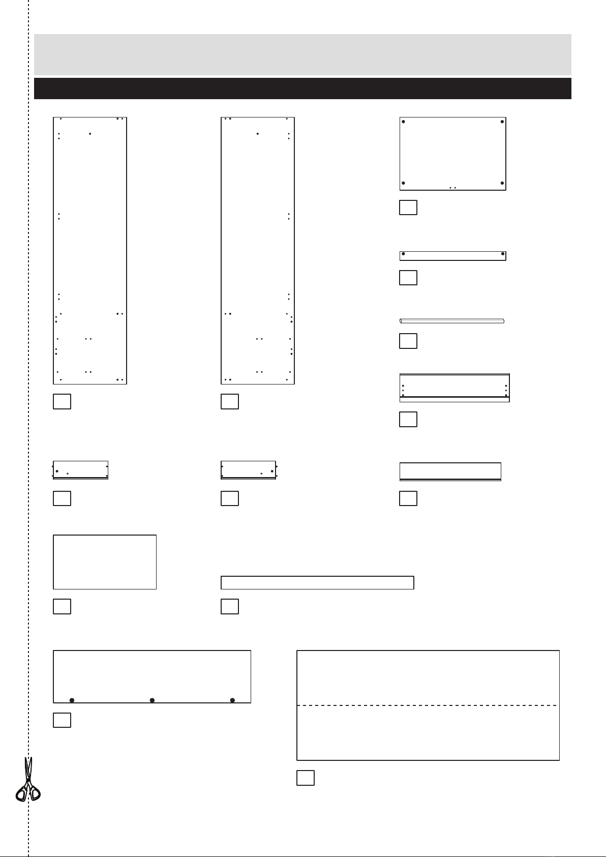
Components - Panels
Please check you have all the panels listed below
2
80%
x 3
If you have damaged or missing components, call the
Customer Helpline: 03456 400800 quoting the reference
numbers below
1 2
4
3
Hanging Rail (FHR710)
(710mm long)
5
10
9
6
12
11
87
13
Top/Base (D1574A)
(718 x 494mm) x 3
Left Side (DF2091A)
(1808 x 496mm)
Rail (D1570A)
(718 x 60mm) x 2
Right Side (DF2093A)
(1808 x 496mm)
Door (DF2094A)
(1338 x 355mm) x 2
Vertical Rail (DF2095A)
(1306.5 x 88mm)
Drawer Back (W686-124)
(686 x 124mm) x 2
Drawer Base (T697-367)
(697 x 367mm) x 2
Left Drawer Side (W370-124LH)
(370 x 124mm) x 2
Drawer Front (DF2092A)
(742 x 192mm) x 2
Right Drawer Side (W370-124RH)
(370 x 124mm) x 2
Back (X1779-744)
(1779 x 744mm)
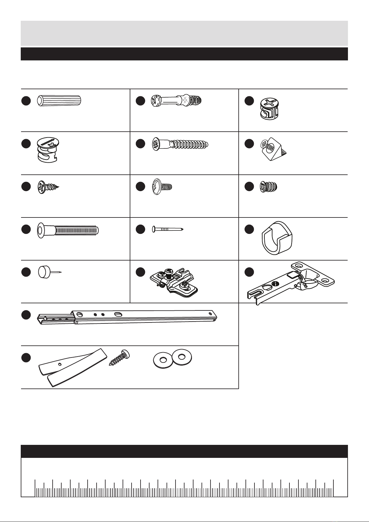
Please check you have all the fittings listed below
3
Components - Fittings If you have damaged or missing components, call the
Customer Helpline: 03456 400800 quoting the reference
numbers below
Note: The quantities below are the correct amount to complete the assembly. In some cases
more fittings may be supplied than are required.
A
Wooden dowel (F22) x 10
B
Metal dowel (F901) x 20
C
D E F
G
P
H
Small locking
nut (F3) x 4
Ruler - Use this ruler to help correctly identify the screws
mm 10 20 30 40 50 60 70 80 90 100 110 120 130 140 150 160 170
Drawer runner (F1004) x 4
Large locking
nut (F900) x 16
M
I
KJ
9mm Screw (F74) x 4 9mm Screw (F73) x 8
Nail (F51) x 26
L
N
Rail holder
(F1014) x 2
40mm Screw (F910) x 4
13mm Screw (F63) x 14
Hinge (F518) x 6
Hinge plate
(F523) x 6
O
Knock-in Peg (F171GY) x 8
Wedgefix (F639) x 8
Plastic Nail (F91) x 4
QStrap Screw Washer x 2
Overbalance protector kit (F269) x 1
Assembly Instructions
4
If you have damaged or missing components, call the
Customer Helpline: 03456 400800 quoting the reference
numbers below
Step 1
80% x 2
x 2
x 2
x 2
x 2
6
B
B
B
C
C
CC
78
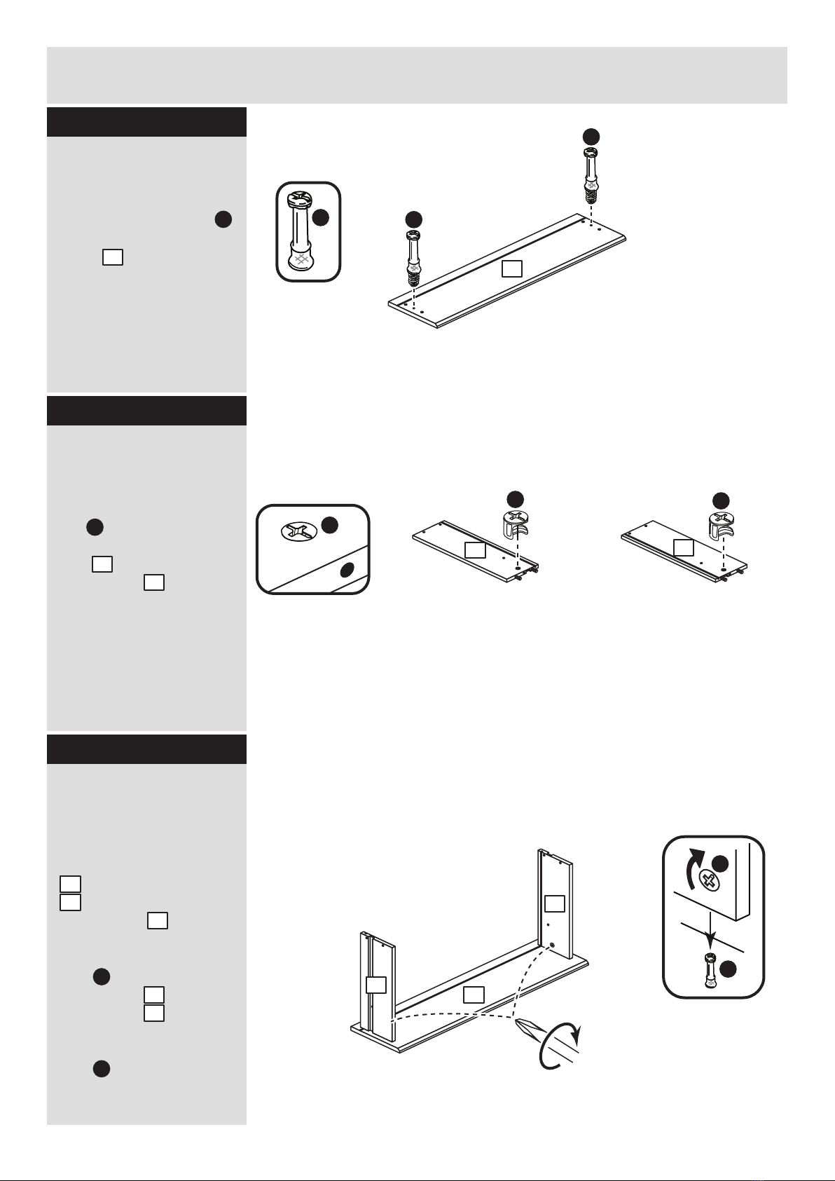
Step 2
Prepare the 2 drawer
fronts
Screw 2 metal dowels
into each of the drawer
fronts .
Note: Tighten the metal
dowels up fully against
the panels.
B
6
Prepare the drawer
sides
Insert a small locking
nut into the hole
shown on the left drawer
side and the right
drawer side .
Note: The arrow on the
locking nut must point
towards the hole in the
edge of the panel.
Step 3
C
7
8
Attach the drawer
sides to the drawer
front
Push the left drawer sides
. and right drawer sides
. onto the back of the
drawer front .
Turn the small locking
nuts on the left
drawer side and right
drawer side .
Note: Turn the locking
nuts clockwise to
secure panels - more
than 1/2 a turn.
7
8
6
C
C
7
8
7
8
B
B
6
J
Assembly Instructions
5
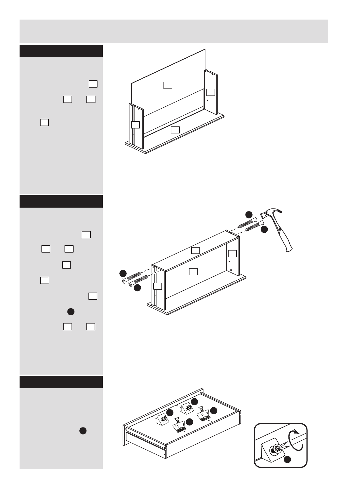
Step 4
J
Fit the drawer base
Slide the drawer base
down the grooves in the
drawer sides and
and down into the
groove in the drawer
front .
Step 5
Fit the drawer back
Fit the drawer back
between the drawer
sides and .
Make sure that the
drawer base fits into
the groove in the drawer
back .
Hold the drawer back
in position and tap the
knock-in pegs
through the holes in the
drawer sides and .
10
7 8
6
9
7 8
10
9
9
J
7 8
Step 6
Fit the wedgefixes
Turn the drawer
assemblies over and
slide 4 wedgefixes
into the front and back
grooves, as shown, and
tighten up the screws.
F
J
J
F
F
F
F
F
10
7
9
7
8
10
8
6
x 2
x 2
x 2
Finished
front edge
Finished
front edge
Assembly Instructions
6
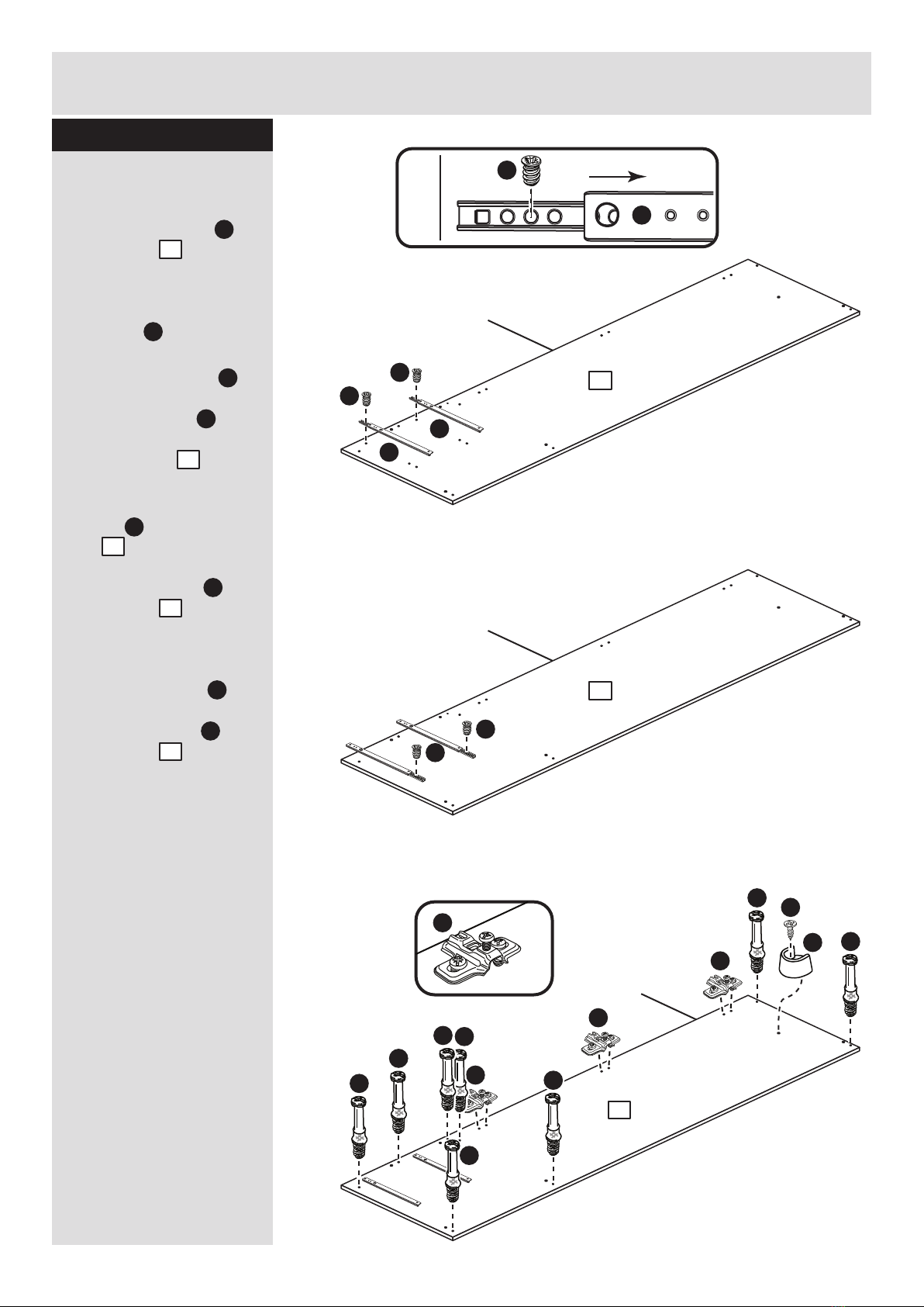
Step 7
Finished
front edge
I
P
a:
b:
c:
Prepare the left side
a: Place 2 runners on
the left side . Slide
back the top of runner
and use the 2nd hole
from the front to fit the
1st screw .
b: Slide the runner
back the other way and
fit the 2nd screw into
the corresponding hole
in the left side .
c: Screw 8 metal
dowels into the left
side .
Push a rail holder into
the left side . Make
sure that it is fitted
straight, in line with the
panel edges and then
secure with screw .
Fit 3 hinge plates onto
the left side , making
sure that the slot is
facing towards the
finished front edge.
1
I
I
B
1
P
P
1
N
L
G
1
N
1
80% x 3
I
P
I
P
1
Finished
front edge
1
I
I
N
N
N
B
B
B
B
B
B
B
B
L
G
1
Assembly Instructions
7
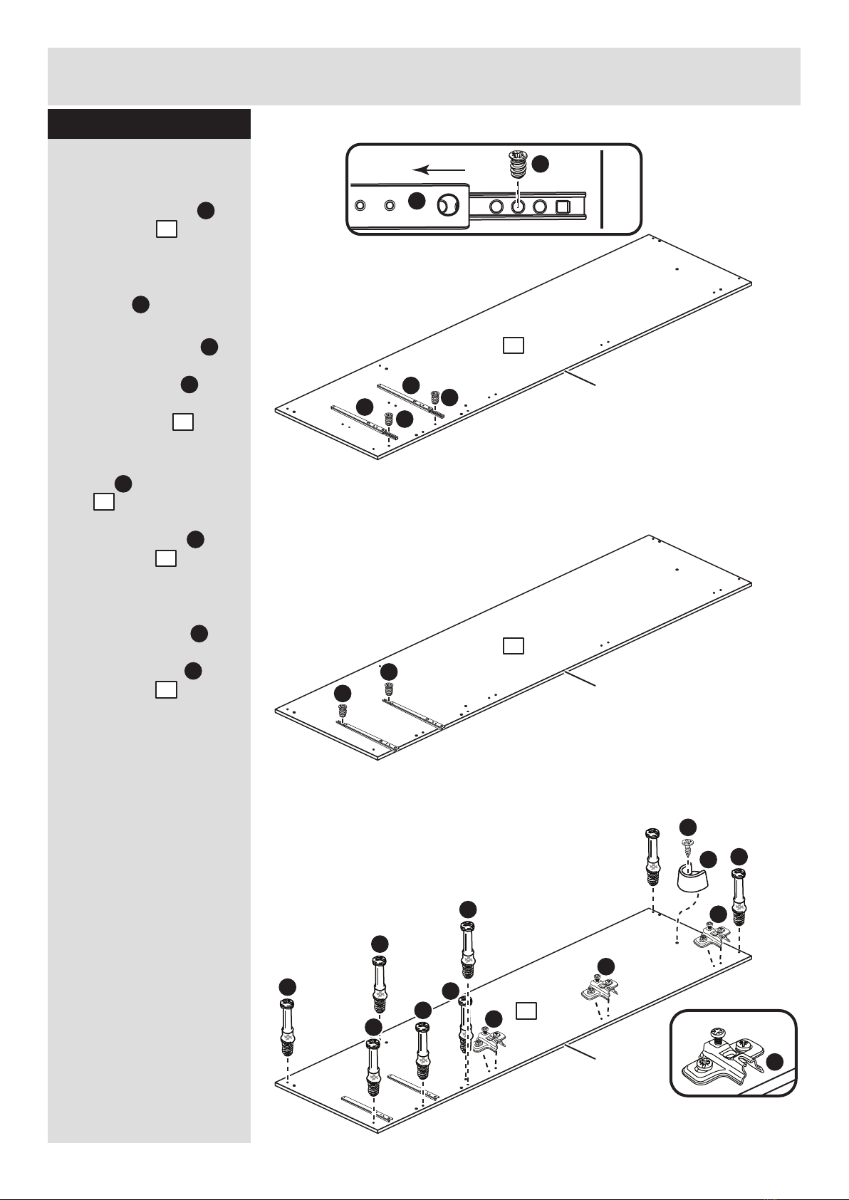
Step 8
Prepare the right side
a: Place 2 runners on
the right side . Slide
back the top of runner
and use the 2nd hole
from the front to fit the
1st screw .
b: Slide the runner
back the other way and
fit the 2nd screw into
the corresponding hole
in the right side .
c: Screw 8 metal
dowels into the right
side .
Push a rail holder into
the right side . Make
sure that it is fitted
straight, in line with the
panel edges and then
secure with screw .
Fit 3 hinge plates onto
the right side , making
sure that the slot is
facing towards the
finished front edge.
2
I
I
B
2
P
P
2
Finished
front edge
I
P
a:
b:
c:
L
2
N
G
2
N
Finished
front edge
I
P
I
P
2
Finished
front edge
2
I
I
Finished
front edge
2
N
N
N
L
G
B
B
B
B
B
B
B
Finished
front edge
Assembly Instructions
8
Step 9
Step 10
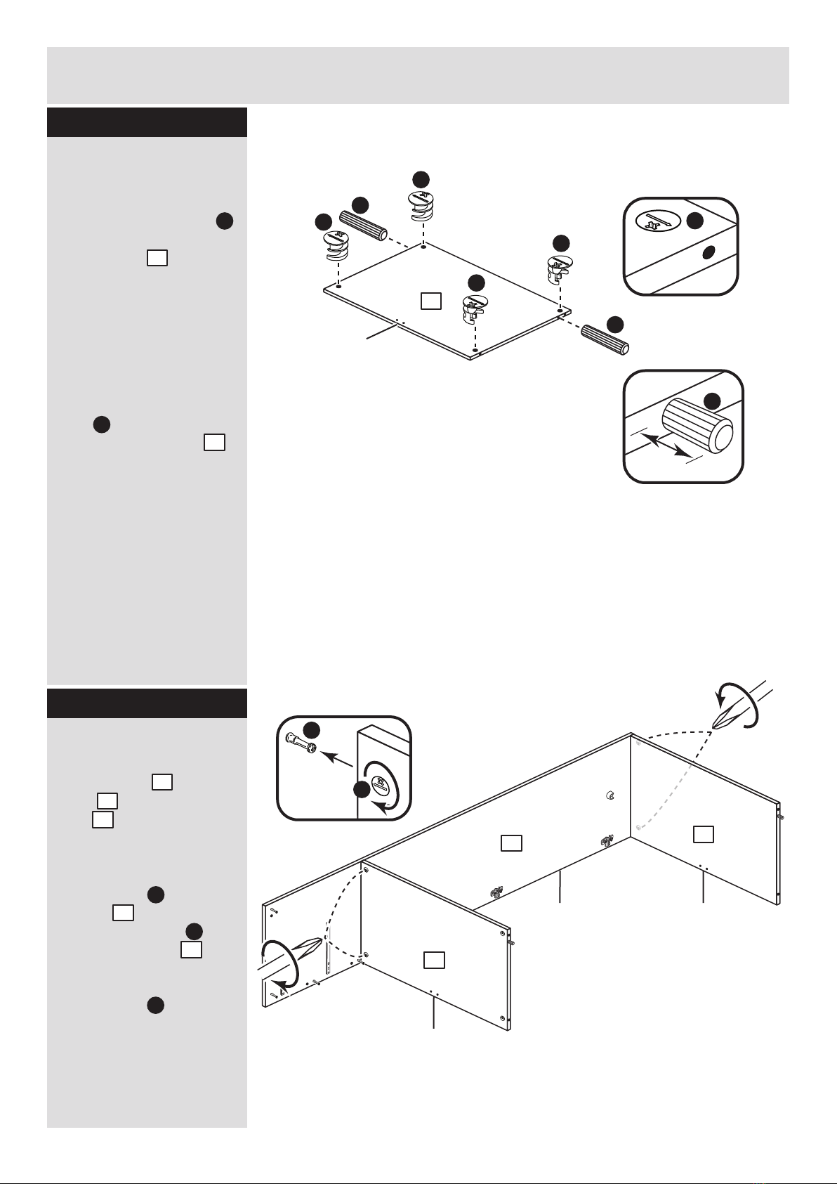
Fit the top and a base
Push the top and
base onto the right
side .
Use a screwdriver to
tighten the 2 large
locking nuts fitted to
the top and the 2
large locking nuts
fitted to the base .
Note: Turn the large
locking nuts as far as
they will go - more than
1/2 a turn.
3
3
2
D
D
3
3
D
Prepare the 3 top and
base panels
Tap 2 wooden dowels
into each of the top and
base panels .
Note: Wooden dowels
must not stick out from
the edge by more than
10mm or they may
damage other panels.
Insert 4 large locking
nuts into each of the
top and base panels .
Note: The arrow on the
locking nut must point
towards the hole in the
edge of the panel.
3
D
D
D
D
D
D
Finished
front edge
A
A
10mm
A
x 3
A
3
3
Finished
front edge
3
Finished
front edge
3
2
B
D
Top
Base
E
E
Assembly Instructions
9
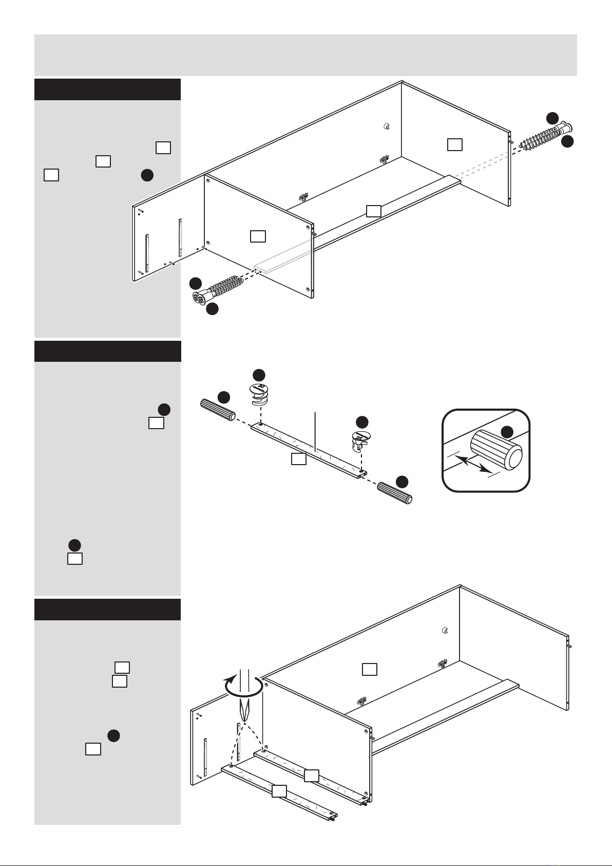
Step 11
Fit the rails
Push the rails onto
the right side .
Use a screwdriver to
tighten the 2 large
locking nuts fitted to
the rails .
4
2
D
4
Step 13
Fit the vertical rail
Attach the vertical rail
to the top and base
. using 4 screws .
11
3
3E
3
3
E
E
11
A
D
A10mm
A
Prepare the 2 rails
Tap 2 wooden dowels
into each of the rails .
Note: Wooden dowels
must not stick out from
the edge by more than
10mm or they may
damage other panels.
Insert 2 large locking
nuts into each of the
rails .
A
4
4
D
4
Plain chipboard
surface
x 2
D
Step 12
2
4
4
This manual suits for next models
2
Table of contents
Other Denver Indoor Furnishing manuals

Denver
Denver 134094 User manual

Denver
Denver DNTB3 User manual

Denver
Denver RTV 2D User manual

Denver
Denver TAQ-10283 User manual

Denver
Denver RTV 2D User manual

Denver
Denver SS 9046 User manual

Denver
Denver wieszak User manual

Denver
Denver SANTANA MIDSLEEPER SS 9036 User manual

Denver
Denver 360/2546 User manual


