Defender 4K1T4Bx User manual


Visit WWW.DEFENDERCAMERAS.COM/SUPPORT to get additional help from the full product manual and support videos
Pg. 1
WHAT’S INCLUDED
NOTE: Some parts listed below show a range based on your system’s conguration
PRODUCT SUPPORT
Model: 4K2T8Bx
• DVR with 2 TB HDD
• (4 - 8) x 4K Analog HD Cameras
• (4 - 8) x 60 ft. BNC Cables
• (1 - 2) x Camera Power Adapters
• (1 - 2) x 4-Way Power Splitter
Model: 4K4T16Bx
• DVR with 4 TB HDD
• (8 - 16) x 4K Analog HD Cameras
• (8 - 16) x 60 ft. BNC Cables
• (2 - 4) x Camera Power Adapters
• (2 - 4) x 4-Way Power Splitter
WHAT YOU’LL NEED
• TV or Monitor
• USB Flash Drive (to complete the DVR activation GUID)
• Hammer Drill & Appropriate Bit
• Phillips (#2) Screwdriver
• Ladder (if required)
• Cable Protectors (if required)
Model: 4K1T4Bx
• DVR with 1 TB HDD
• (1 - 4) x 4K Analog HD Cameras
• (1 - 4) x 60 ft. BNC Cables
• 1 x Camera Power Adapter
• 1 x 4-Way Power Splitter
Scan this QR code for instant
access to all 4K Support Videos,
Manuals and FAQs.
All kits include the following items:
1 x HDMI Cable, 1 x Ethernet Cable, 1 x DVR Power Supply, 1 x USB Mouse, 1 x Quick Start Guide, 1 x Window Warning Sticker
FCC / IC STATEMENT
This device complies with part 15 of the FCC Rules. Operation is subject to the following two conditions: (1) This device may not cause harmful
interference. (2) This device must accept any interference received, including interference that may cause undesired operation.
FCC WARNING
This equipment has been tested and found to comply with the limits for a Class B digital device, pursuant to Part 15 of the FCC Rules. These limits are
designed to provide reasonable protection against harmful interference in a residential installation. This equipment generates, uses and can radiate radio
frequency energy and, if not installed and used in accordance with the instructions,may cause harmful interference to radio communications. However,
there is no guarantee that interference will not occur in a particular installation. If this equipment does cause harmful interference to radio or television
reception, which can be determined by turning the equipment o and on, the user is encouraged to try to correct the interference by one or more of the
following measures:
• Reorient or relocate the receiving antenna.
• Increase the separation between the equipment and the receiver.
• Connect the equipment into an outlet dierent from that to which the receiver is connected.
• Consult the dealer or an experienced radio/TV technician for help.
IC STATEMENT / DÉCLA RATION IC:
This device contains licence-exempt transmitter(s)/receiver(s) that comply with Innovation, Science and Economic Development Canada’s licence-exempt
RSS(s). Operation is subject to the following two conditions: (1)This device may not cause interference.(2)This device must accept any interference, including
interference that may cause undesired operation of the device.
L’émetteur/récepteur exempt de licence contenu dans le présent appareil est conforme aux CNR d’Innovation, Sciences et Développement économique
Canada applicables aux appareils radio exempts de licence. L’exploitation est autorisée aux deux conditions suivantes :(1)L’appareil ne doit pas produire
de brouillage; (2)L’appareil doit accepter tout brouillage radioélectrique subi, même si le brouillage est susceptible d’en compromettre le fonctionnement.
This equipment complies with IC RSS-102 radiation exposure limits set forth for an uncontrolled environment. This equipment should be installed and
operated with minimum distance 20cm between the radiator and your body.
Cet équipement est conforme aux limites d’exposition aux radiations IC CNR-102 établies pour un environnement non contrôlé. Cet équipement doit être
installé et utilisé avec une distance minimale de 20 cm entre le radiateur et votre corps.

Visit WWW.DEFENDERCAMERAS.COM/SUPPORT to get additional help from the full product manual and support videos
Pg. 2
4CH & 8CH WHITE PLASTIC DVR SETUP
PLEASE READ FIRST!
You must connect your DVR to a monitor/TV to complete the setup. We recommend verifying all accessories and
completing DVR setup before installation. For your best viewing experience, we recommend using a 4K TV or monitor
to view your footage.
1. Connect the monitor, USBmMouse, cameras, modem/router, and power to the DVR based on the color and image
labels:
ACameras: Connect the BNC (YELLOW) connector to the camera and DVR. Connect the power (RED)
connector to the camera and power adapters.
B Camera Power: Connect the Camera to the 4-Way Power Splitter(s) and the Camera Power Adapter(s) to a
power outlet.
CMonitor: Connect the HDMI (BLUE) cable to the DVR and monitor (not included).
DUSB Mouse: Connect the USB mouse (GREEN) to the DVR.
EModem/Router: Connect the Ethernet cable (PURPLE) to the Ethernet port (RJ45) on the DVR and your modem/
router. (NOTE: Wired Ethernet connection required, DVR cannot connect to the modem/router via Wi-Fi.)
FDVR Power: Connect the DVR power cable to a power outlet.
4K Monitor/TV
(not included)
A
B
E
F
D
C
2. Follow the Activation and Setup Wizard on the monitor/TV to set up the DVR. NOTE: YOU WILL NEED A USB FLASH
DRIVE TO COMPLETE THE SET UP (Not included)
APower LED: indicates the DVR is ON
BData LED: data is being read or written to HDD
CNetwork LED: DVR is connected to a network
A
B
C

Visit WWW.DEFENDERCAMERAS.COM/SUPPORT to get additional help from the full product manual and support videos
Pg. 3
8CH & 16CH BLACK METAL DVR SETUP
PLEASE READ FIRST!
You must connect your DVR to a monitor/TV to complete the setup. We recommend verifying all accessories and
completing DVR setup before installation. For your best viewing experience, we recommend using a 4K TV or monitor
to view your footage.
1. Connect the Monitor/TV, USB mouse, cameras, modem/router, and power to the DVR based on the color and
image labels:
ACameras: Connect the BNC (YELLOW) connector to the camera and DVR. Connect the power (RED)
connector to the camera and power adapters.
B Camera Power: Connect the Camera to the 4-Way Power Splitter(s) and to a power outlet.
CUSB Mouse: Connect the USB mouse (GREEN) to the DVR.
DMonitor/TV: Connect the HDMI (AQUA) cable to the DVR and monitor/TV (not included).
EModem/Router: Connect the RJ45 port of the Ethernet (PURPLE) cable to the DVR and modem/router.
(NOTE: Wired Ethernet connection required, DVR cannot connect to the modem/router via Wi-Fi.)
FDVR Power: Connect the DVR power cable to a power outlet.
GPower Switch: Turn the DVR power switch ON. Turn on the monitor/TV.
4K Monitor/TV
(not included)
A
B
E
F
G
DC
2. Follow the Activation and Setup Wizard on the monitor/TV to set up the DVR. NOTE: YOU WILL NEED A USB FLASH
DRIVE TO COMPLETE THE SET UP (Not included)
APower LED: (White) the DVR is ON
BData LED: (Red) data is being imported/exported
CNetwork Connection LED: (White) DVR is connected
to a network
DUSB Port: (USB Flash drive not included)
A
B
C
D
Visit WWW.DEFENDERCAMERAS.COM/SUPPORT to get additional help from the full product manual and support videos
Pg. 4
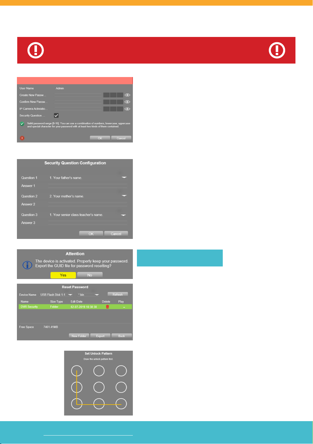
1. ADMIN PASSWORD
• Create your DVR password (the system does not have a
default password it must be created) – PLEASE REMEMBER
YOUR PASSWORD! Defender cannot reset your
password for you.
• Conrm the password.
• Create an IP Camera Activation code (this is only to complete
this screen – IP cameras are not available from Defender for
the 4K system).
• Make sure the Security Question check-box is enabled.
2. SECURITY QUESTIONS
• Select 3 Questions and enter your Answers.
• Security Questions can be used to access your system if you
forget your password.
• REMEMBER YOUR ANSWERS!
RECOMMENDED - GUID Export
• Use the export option to save your Password and Security
Questions to a USB Flash Drive. These settings can be imported
later if you Forgot Password and Import GUID.
• Insert your USB Flash Drive in the DVR and click Yes.
• Device Name should be the name of the USB.
• Select the le type *.bin.
• Click Export to copy the Security Settings to the USB Flash Drive.
3. UNLOCK PATTERN
• Draw an Unlock Pattern to access your system instead of
entering the password.
• Click & Drag to draw the pattern – you must connect at least
4 dots.
WARNING : DO NOT RIGHT CLICK ON THE SCREEN BECAUSE YOU
WILL BE UNABLE TO COMPLETE THE SECURITY QUESTIONS.
DVR ACTIVATION
Activation
Visit WWW.DEFENDERCAMERAS.COM/SUPPORT to get additional help from the full product manual and support videos
Pg. 5
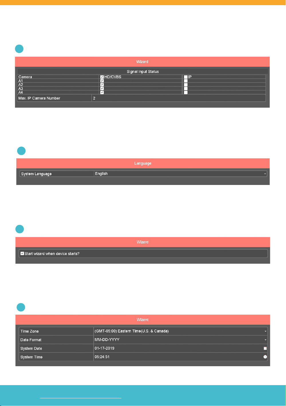
DVR SETUP WIZARD
1SIGNAL INPUT STATUS
Displays the type of camera that can be connected to the DVR. All cameras should be HD/CVBS. IP Cameras are not
available from Defender for the 4K Systems.
2LANGUAGE
Select the System Language. The DVR Menu will show in the language selected.
3WIZARD
Select the check-box if you want the Setup Wizard to show every time the DVR is powered On.
4TIME & DATE FORMAT
Select your Time Zone, Date Format, System Date, and System Time.
Visit WWW.DEFENDERCAMERAS.COM/SUPPORT to get additional help from the full product manual and support videos
Pg. 6
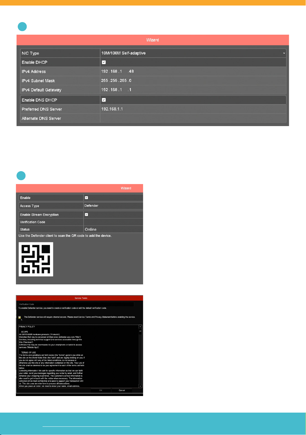
5NETWORK CONNECTIONS
Displays the IP and server address details form your network when the DVR is connected to your modem/router.
Changes are only required if you use a static IP address.
6MOBILE APP ACCESS
Select Enable to allow the Defender 4K system to be
paired with the Defender 4K app. Ensure that your DVR
is connected via the Ethernet port to an active Internet
connection for this step to work.
Once you check the Enable box for the Mobile App
Access, our Service Terms screen will pop up. You will
need to check the box and set up a verication code on
the top of the page in order to click Ok and get back the
the previous screen.
To opt out of mobile App access, leave the Enable box
unchecked and go directly next step.
Visit WWW.DEFENDERCAMERAS.COM/SUPPORT to get additional help from the full product manual and support videos
Pg. 7
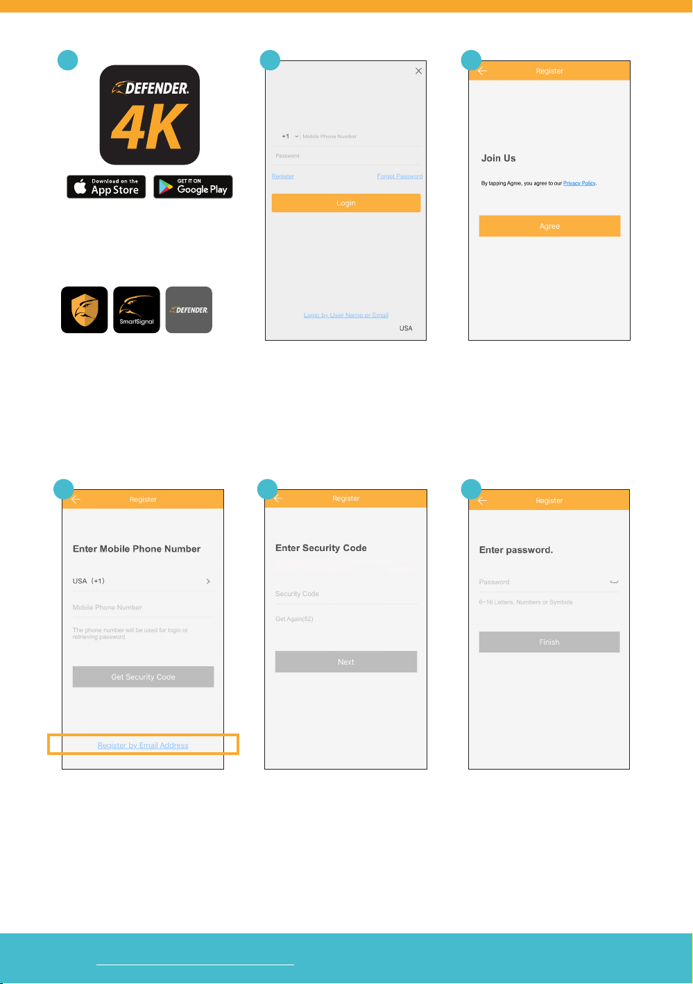
6.1
Download the Defender 24-7 mobile
app from your app store. Open the
app on your device.
DO NOT DOWNLOAD:
Enter your Mobile Number or Email.
Register your account.
Enter the Security Code sent to
your phone or email.
NOTE: The code is valid for 30
mins. Please check your junk mail
Review the Privacy Policy.
Enter a Password for the app.
6.3
6.66.56.4
6.2
Visit WWW.DEFENDERCAMERAS.COM/SUPPORT to get additional help from the full product manual and support videos
Pg. 8
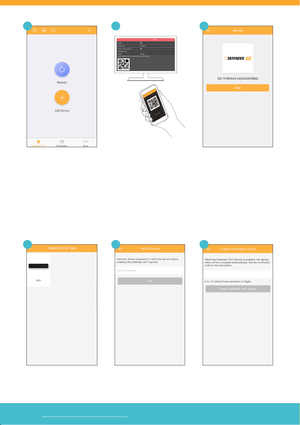
Tap the (+) icon to add the DVR.
Tap DVR.
Scan the QR Code displayed on the
DVR setup screen. Alternatively, you
can access the QR code from the
menu via Conguration > Network >
App Access
Enter the DVR Password.
(Created during the DVR setup)
Tap Add to start connecting.
Enter the Verication Code.
(Created during the DVR setup)
6.9
6.12
6.8
6.11
6.7
6.10
This manual suits for next models
1
Table of contents
Other Defender Security Camera manuals

Defender
Defender GUARD IP4MCB1 User manual

Defender
Defender 21060 User manual

Defender
Defender PH300 User manual

Defender
Defender GUARD IP4MCB1 User manual

Defender
Defender SP301-C User manual

Defender
Defender PH301 User manual

Defender
Defender 82-12165 User manual

Defender
Defender GUARD IP4MCB1 User manual

Defender
Defender Guard Pro User manual

Defender
Defender GUARD IP4MCB4 User manual


