Craden DP8 User manual

CRADEN
P E R I P H E R A L S
C O R P O R A T I O N
DP8 & DP9
DOCUMENT PRINTERS
TECHNICAL MANUAL
P/N 99090 REVISION 7 7/2007
7860 AIRPORT HIGHWAY, PENNSAUKEN, NJ 08109
(856) 488-0700 (856) 488-0925 FAX
www.craden.com

WARNING
This equipment generates, uses and can radiate radio frequency energy and, if not installed in
accordance with the instruction manual, may cause interference to radio communications. It has
been tested with a Class A computing device and has been found to comply with Part 15 of FCC
rules, which are designed to provide reasonable protection against such interference when operated
in a commercial environment. Operation of this equipment in a residential area is likely to cause
interference in which case the user at his own expense will be required to correct the interference.
RECORD OF CHANGES
REVISION DATE ECO’s PAGES AFFECTED NOTES
1 10/01 ALL Initial Release
2 11/02 ALL Add DP9
3 06/03 1, 6, 7, 12-15 Fast Draft speed
4 01/04 1-3, 6-9, 16, 17, 22, 30, 32 Updated
40, 41, All Tech Dwgs.
5 09/04 1, 4, 7, 8, 26, 30, 34, 37, Add edge sensing,
38, 41 Several Tech Dwgs. Updated
6 02/06 3, 4, 7-10, 20, 25, 27-29, Updated
31-33, 37, 38, 39
Several Tech Dwgs.
7 07/07 ALL Updated

DP8 & DP9 Technical Manual Table of Contents
1.0 DP8 & DP9 DOCUMENT PRINTERS - FUNCTIONAL SPECIFICATIONS 1
2.0 INSTALLATION
2.1 INSTALLATION PROCEDURE 2
2.2 RESHIPMENT 3
3.0 OPERATION
3.1 RIBBON CARTRIDGE LOADING 3
3.2 KEYPAD OPERATION 4
3.3 DISPLAY OPERATION 4
3.4 DOCUMENT INSERTION 5
3.5 CONFIGURATION 5
3.5.1 Printer Parameters 6
3.5.2 Communication Parameters 7
3.5.3 Override Parameters 7
3.5.4 Service Parameters 8
3.6 DIAGNOSTICS
3.6.1 Power Up Diagnostics 8
3.6.2 Enhanced Diagnostics 9
3.7 SELF TEST 9
3.8 LOCAL PRINTING 9
3.9 ERROR CONDITIONS
3.9.1 Document Jam 9
3.9.2 Cover Open 9
3.9.3 Page Overflow 9
3.9.4 Carriage Fault 9
3.9.5 Clear Eject Jam 9
3.9.6 Narrow Document 9
3.10 PROGRAMMING 10
3.10.1 Command Summary 10
3.10.2 Document Movement Commands 11
3.10.3 Print Commands 12
3.10.4 Low Density Graphics Commands 14
3.10.5 High Density Graphics Commands 14
3.10.6 Display Commands 14
3.10.7 Configuration Commands 15
3.10.8 Status and Keypad Commands 15
3.11 Drivers 16
3.11.1 Installing Craden Drivers on WINDOWS 95 OR 98 16
3.11.2 Installing Craden Drivers on WINDOWS NT, 2000 OR XP 17
3.11.3 Installing Craden USB Drivers on WINDOWS NT, 2000 OR XP 17
3.11.4 Using Printer Resident Device Fonts 17
3.11.5 Writing to the Printer LCD Display 18
3.12 INTERFACING 18
3.12.1 Input Buffer Operation 18
3.12.2 Interface Protocols 18
3.12.3 Interface Signals & Cables 19
3.13 PROBLEM SOLVING 19
3.13.1 No Display or Blocks Displayed 19
3.13.2 Unchangeable Configuration Parameters 19
3.13.3 No Document Motion 20
3.13.4 Carriage Fault or No Carriage Motion 20
3.13.5 No Printing or Light Printing 20
3.13.6 Ribbon Smear 20

3.13.7 Erratic Document Feed, Mispositioning or Overprinting 20
3.13.8 Rollers Run at Power-Up or After Document Ejected 20
3.13.9 Erratic Character Spacing or Carriage Hitting End Stops 20
3.13.10 Interface Inoperative 20
4.0 THEORY OF OPERATION
4.1 OVERVIEW 21
4.1.1 Carriage Drive Assembly 21
4.1.2 Document Drive Assembly 21
4.1.3 Switching Power Supply 21
4.1.4 Main Printed Circuit Board 22
4.1.5 Keypad/Display Assembly 22
4.2 ELECTRONICS IN DETAIL
4.2.1 Low Voltage Supplies 22
4.2.2 Microprocessor System 22
4.2.3 Stepper Motor Drivers 22
4.2.4 Printhead Drivers 25
4.2.5 Keypad and Display 25
4.2.6 Sensors 25
4.2.7 Character Printing 25
5.0 MAINTENANCE
5.1 LUBRICATION AND CLEANING
5.1.1 Lubrication 27
5.1.2 Document Feed Roller Cleaning 27
5.1.3 Sensor Cleaning 27
5.1.4 Printhead Cleaning 28
5.1.5 Document Print Area Cleaning 28
5.1.6 Cabinet Exterior Cleaning 28
5.2 SERVICE PARAMETER SET-UP PROCEDURE 29
5.3 ELECTRICAL ADJUSTMENTS 29
5.4 MECHANICAL ADJUSTMENTS
5.4.1 Printhead Gap 30
5.4.1.1 Ribbon Shield Removal/Replacement 31
5.4.1.1.1 Ribbon Shield Face Inspection 32
5.4.2 Carriage Drive Belt Tension 33
5.4.3 Document Drive Belt Tension 33
5.4.4 Carriage Shaft Cam and Shaft Rack 33
5.4.5 Rear Document Roller Spring Force 33
5.4.6 Auto Alignment Gate Ramp 34
5.4.7 Auto Alignment Gate Height 34
5.4.8 Front Document Roller Spring Force 35
5.4.9 Auto Alignment Skew Sensor Calibration 35
5.5 REPLACEMENT PROCEDURES
5.5.1 Cabinet 35
5.5.2 Main PCB 35
5.5.3 Sensor PCB 36
5.5.4 Keypad 36
5.5.5 Display 36
5.5.6 Power Supply PCB 36
5.5.7 Carriage Motor 36
5.5.8 Document Motor 37
5.5.9 Printhead 37
5.5.10 Carriage Drive Belt 37
5.5.11 Document Drive Belt 37

5.6 TROUBLESHOOTING
5.6.1 Basic Troubleshooting Procedure 38
5.6.2 No Display 38
5.6.3 Defective Keypad 38
5.6.4 Defective Sensor 39
5.6.5 No Document Motion 39
5.6.6 No Carriage Motion 40
5.6.7 No Print or Light Print 40
5.6.8 Print Quality 40
5.6.9 Missing Dots 41
5.6.10 Erratic Document Feed or Mispositioning 41
5.6.11 Erratic Character Spacing or False Document Jams 41
5.6.12 Interface Inoperative 41
5.6.13 Diagnostic Flowchart 42
5.7 RECOMMENDED SPARE PARTS 43
5.8 RECOMMENDED SERVICE TOOLS 43
6.0 MAJOR ASSEMBLY ILLUSTRATIONS & PARTS LISTS
Printer Diagram 44
Major Assembly Tree 45
73802 Carriage 46
73804 Box 47
73806 Carriage Drive 49
73809 Lower Drive 50
73810 Document Drive 51
73815 Keypad/Display 52
73816 Electromechanical 53
73819 Printer 54
72135 Main PCB (including 72133 keypad and schematics) 55

DP8 & DP9 DOCUMENT PRINTERS - FUNCTIONAL SPECIFICATIONS
1.1 Print Characteristics
Print Method 24-wire dot matrix impact, automatic thickness compensation
Print Spacing 5, 6, 8.5, 10, 12, 17, 20 and 24 chars/inch
Fonts 96 char. ASCII, international character set
Windows True Type & graphics
Print Speed Characters/inch Correspondence Normal Draft
(chars/second) 10 75 150 225
12 90 180 270
Dot Graphics 60,120,180, 360 horizontal; 72, 180 vertical
(dots/inch)
Feed Speed 50 mSec. single line feed at 5 or 6 lines/inch
12 inches/second (305 mm/sec) slew speed
Feed Accuracy +/- 0.6%
Ribbon Cartridge life DP8: 3 million characters, DP9: 5 million characters
1.2 Document Characteristics
Media Single sheets, multipart forms (up to 6 parts), passbooks & envelopes
Print Line Width DP8: 5.6” (142mm), DP9: 8.2” (208mm)
Form Width 2.5” (64 mm) to 6.5” (165mm) in DP8 or 9.7” (246mm) in DP9
DP8: wider forms printable in landscape mode
Form Height 2.5” (64 mm) minimum, no maximum
Form Thickness 0.0035” (0.09 mm) to 0.062” (1.57 mm)
Non-printable areas Top of form 0.16” (4.1mm)
Above horiz. fold 0.38” (9.7mm)
Below horiz. fold 0.30” (7.6mm)
Bottom of form 0.45” (11.4mm)
Vertical fold/edge 0.25” (6.4mm)
1.3 Interface
Standard Serial RS-232, 1200-38400 baud, 11KB buffer, dual ports on DP9
Command Sets IBM Proprinter/4722, Unisys and Craden
Protocols DTR, Xon/Xof
Optional USB port, Parallel port
Power Input 100-240 VAC, 43-63 Hz, 80 W max.
1.4 Physical Characteristics
Dimensions DP8: 10.6” (269mm) wide, 7.2” (183 mm) deep, 7” (178 mm) high
DP9: 13.8” (351mm) wide, 9.8” (249mm) deep, 7.2” (184mm) high
Weight DP8: 11 pounds (5 kg) + 1.3 pounds (0.6kg) packing
DP9: 14.4 pounds (6.5 kg) + 3.4 pounds (1.5 kg) packing
1.5 Environment & Standards
Operating 10 to 40°C, 10 to 90% humidity
Storage -30 to 70°C, 5 to 95% humidity
Standards UL 1950 & Canadian UL Listed
FCC 20780 Class A certified
IEC 950 & CE certified
1

2.0 INSTALLATION
2.1 Installation Procedure
1. Read 3.1 to 3.5.2 on Operation and Configuration.
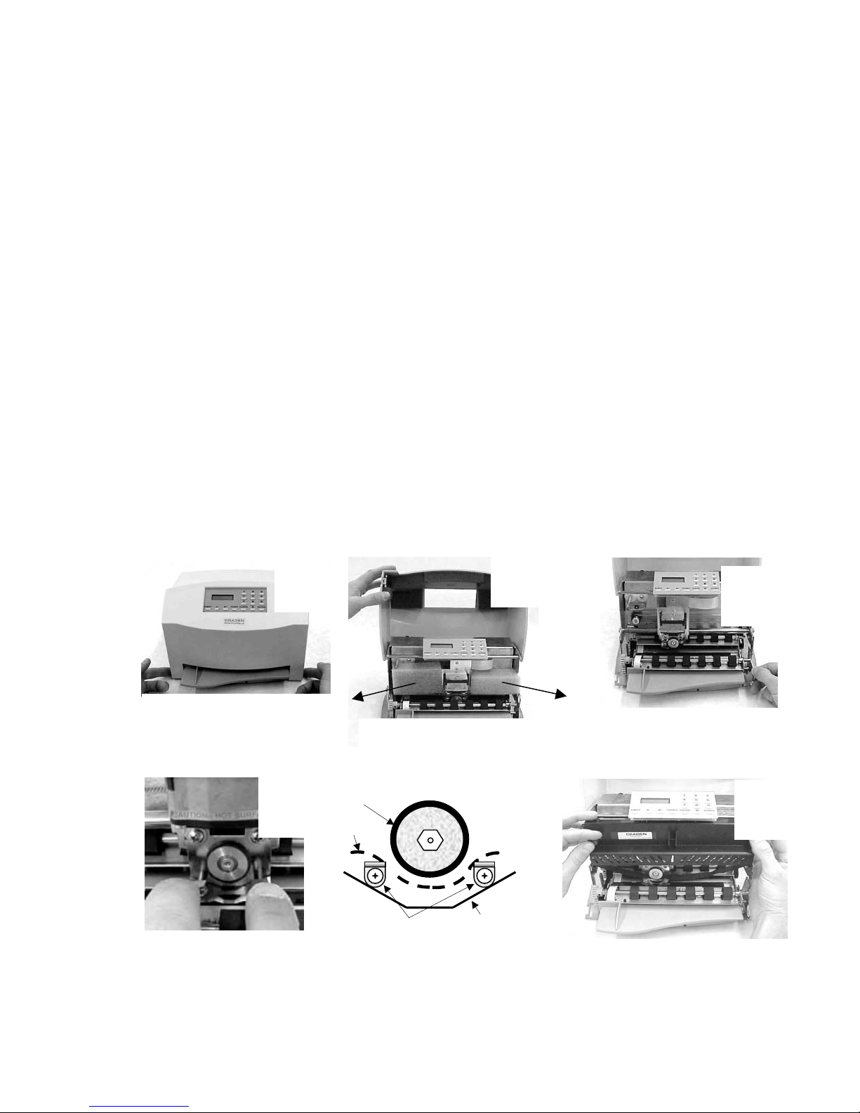
2. Press the cabinet latches on the lower front cabinet sides and rotate the cabinet upwards.
3. Remove the foam blocks on each side of the carriage.
4. Install the ribbon cartridge (See 3.1)
5. Connect the interface cable. (See 3.11.3 for cabling information).
6. Check that the power switch on the printer rear is off (“0” side depressed). Connect the line
cord between the printer and an electrical outlet. The printer accepts 110 to 240VAC
nominal input. If a line cord was not supplied with the printer procure an IEC HAR line cord
that has an IEC 320-C13 style connector and the appropriate HAR plug for your country.
7. Turn on the power switch. READY should appear on the display. If the display is not legible
adjust the contrast knob located on top of the mechanism beneath the cabinet.
8. Configure printer and interface parameters (See 3.5-3.5.2) using 92 and 93 FUNCT.
Common variations to the default settings are a higher baud rate for better throughput,
EMULATION MODE I for Proprinter emulation and PROTOCOL = XON/XOF for software
that does not use DTR hardware handshaking. Function 94 settings are factory set for a
specific printer and should not be changed.
9. Perform a local print test (See 3.8) with 95 FUNCT.
10. If host printing is incorrect, check that 93 FUNCT Communication Parameters match the
host parameters and review all 92 FUNCT Printer Parameters.
Push in on cabinet latches
Rotate cabinet up and back.
1
Rotate lift ring forward to lift
and lock carria
g
e.
3
Push ribbon guide plate tabs
down.
4
Rotate cartridge into place and snap in.
Rotate cartridge drive gear clockwise to
align and take up ribbon slack. Push
shield up. Lower carriage into operating
position. Close cabinet.
6
2
Remove foam shipping blocks.
5
RUBBER
WHEEL
RIBBON
SHIELD
TABS
RIBBON
PATH
Slip ribbon over and behind
guide plate tabs.
2

2.2 Reshipment
If possible, retain the original packing material for reshipment. If the original packing material is
not used, insure that printer and the printer carriage will not move during shipment and that the
unit has sufficient protective padding.
3.0 Operation
3.1 Ribbon Cartridge Loading
Generic ribbons may cause printer malfunctions including ribbon stalling, poor print
quality, smearing, and printhead failures. Please use Craden ribbons or carefully qualify
generic ribbons.
To replace a ribbon cartridge, do the following and refer to the drawings on page 2 and
above:
1. Depress the cabinet latches on the lower front cabinet sides and rotate the cabinet
upwards.
2. Pull the lift ring on the right side of the printer forward to lift and lock the carriage.
3. Push down the ribbon guide tabs on each side of the printhead to lower the ribbon shield.
4. Remove the old cartridge by pulling down on the top and rotate the top edge forward.
5. Guide the new ribbon behind the rubber wheel and over ribbon guide tabs. Insure the ribbon
is not twisted.
6. Mount the new ribbon cartridge bottom edge first and rotate the top edge backwards. Turn
the cartridge knob clockwise if necessary to lock the cartridge in place.
7. Turn the cartridge knob clockwise to remove the ribbon slack.
8. Push the ribbon shield up and the lift ring backward to lower the carriage. Push down on the
cartridge to insure that the carriage is fully seated.
9. Rotate the cabinet forward until the latches on both sides engage.
Ribbon guide & shield
DP9 printer with cabinet open, lift ring down and
ribbon guide down
Lift
Ring
Ribbon
Cartridge
Printhead
DP9 Ribbon
Fit, Sides
Tabs
DP8 Ribbon
Fit, Sides
Tabs
Cartridge
Cli
p
3

3.2 Keypad Operation
EJECT: ejects an inserted document if the print buffer is empty. Should a document remain
partially in the printer, press eject again to fully eject paper. If ‘CLEAR EJECT
JAM” is displayed, press the CLEAR key and EJECT again.
↑A: moves a document up 1/60" with each depression. If held depressed, the document
will slowly move into the printer. Also initiates document insertion if the printer is
configured for key rather than automatic insertion. (See 3.5.1)
↓B: moves a document down 1/60" with each depression. If held depressed, the
document will slowly move out of the printer.
FUNCT: enters previously keyed digits as a function code. All function codes beginning with 9
are reserved for internal printer operations. All other function codes are transmitted
to the host system and their usage is host defined. If no digits have been entered,
FUNCT will override automatic alignment for one document.
CLEAR: erases any previously keyed digits before they are transmitted to the host by the
FUNCT or ENTER keys.
ENTER: transmits previously keyed digits to the host system. All responses are host defined.
This key also initiates document printing if the printer is configured to delay printing
until the ENTER key is pressed (See 3.5.1).
0 to 9: enter digits to be transmitted to the host by the FUNCT or ENTER keys. Key
depressions appear on the lower display line.
3.3 Display Operation
The display has 2 lines of 16 characters each and is used to display messages both from the
printer and the host system. There is a contrast knob to the left of the ribbon
instruction/configuration label that should be adjusted for maximum legibility depending on the
display viewing angle. See the printer diagram on page 43. When the printer is turned on,
"READY" will be displayed.
DP9 printers have green lamps to identify which port is active when DUAL PORT is set to Y
(see 3.5.2). The lamp labeled “A” indicates the port closest to the printer’s left side is active
and the lamp labeled “B” indicates the port closest to the printer’s right side is active.
Keypad & Display Panel
If one of the green lights is on and there is no paper in the printer, there is more print pending.
Insert paper and the printer will finish printing.
4

3.4 Document Insertion
Insertion procedures may be customized to satisfy varied applications and user preferences.
(See the Printer Parameters in 3.5.1).
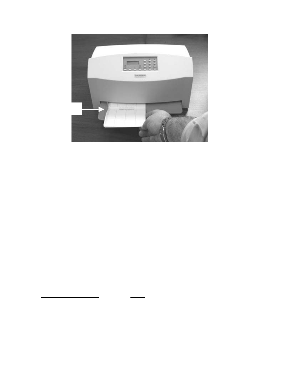
If auto alignment is enabled, gently insert the document upper left corner toward the point
where the left edge guide and the feed rollers meet. Release the document when the rollers
grip it and it will be automatically aligned and inserted to the first print line.
Auto alignment may be disabled for an individual document by pressing the FUNCT key before
insertion or for all documents by changing the SKEW CORRECT printer parameter. When
auto alignment is disabled, the left document edge should be aligned to the left edge guide
and then slid forward into the feed rollers which will insert it to the first print line.
The PAUSE printer parameter may be set to delay when the rollers activate for a few seconds
or until the A↑key is pressed. This allows more time to insert cumbersome documents or to
train new users. With auto alignment enabled the printer should be configured for no delay.
The DOCUMENT INSERT printer parameter may be set to move the document to the last
(bottommost) rather than the first printable line.
The BEGIN PRINTING printer parameter may be set to delay printing until ENTER is pressed.
This allows the operator to insure that the document has inserted correctly. If not, it may be
EJECTed and reinserted.
3.5 Configuration
The printer may be configured from the keypad with all parameters saved in a non-volatile
memory. There are 4 configuration categories:
Configuration Category Press
Printer Parameters 9 2 then FUNCT
Communication Parameters 9 3 then FUNCT
Override Parameters 9 9 then FUNCT
Service Parameters 9 4 then FUNCT
After accessing a category, each parameter will be displayed. Press A↑to display the next
choice for the parameter or press ENTER to display the next parameter. If the display does not
change when A↑is pressed, the keypad is locked. See 3.5.3 to unlock the keypad.
Document edge
g
uide
5
Other manuals for DP8
5
This manual suits for next models
1
Table of contents
Other Craden Printer manuals