6
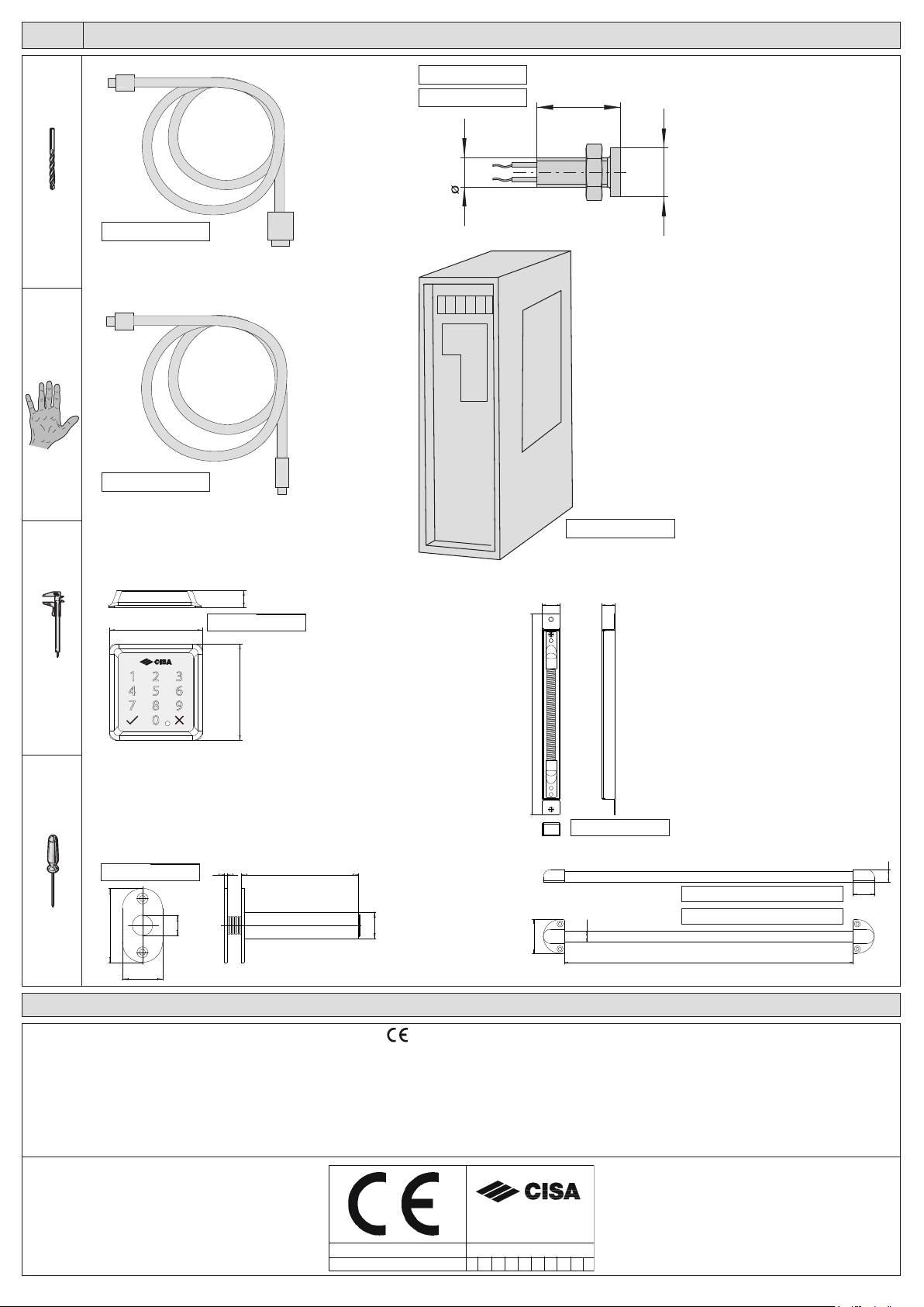
The cable supplied can be connected with the existing electric system.
Check the maximum length of the cables with the table.
WARNING:
CISA declines all responsibility for the compliance of the
existing system to current regulations.
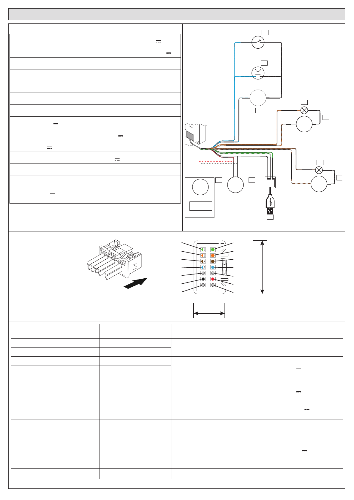
Cable section (mm²) Max length (m) (*)
0,5 5
0,75 10
115
1,5 or higher 25
(*) The table gives the minimum section of the cables depending on the length
of the cable to connect with the cable supplied.
WARNING:
Use the cable supplied with the lock only.
We recommend using cable guards (see the accessories section) for the power supply cable between the frame and the door.
The motor must be powered at all times, even when the door is open.
The power supply is not supplied with the kit.
See item 1.07060.10.0 in the accessories section.
WARNING: A power supply with the following characteristics is recommended:
Output: 12V - 2A
Protection with fuse 2A, 250V
Protection: OVP (overvoltage), OCP (overcurrent)
Certications: CE, in compliance with directives 2014/30/EU, 2014/35/EU Class 2 (double insulation), LPS source (in compliance with IEC
62368), SELV, UL Listed or UL Recognized.
OPERATION
The panic exit device has the same features as the mechanical version, in compliance with EN1125, with an additional power-
assisted opening function thanks to the interaction between the mechanics and the electronics.
INTERFACING FOR OPENING
The panic exit device is opened by pressing button 1 or opening switch 2 (see diagram 1).
1. Single opening: when button 1 is pressed, the panic exit device opens for 3 seconds (this time can be set up to 180 sec on the PC), after
which it closes and the latchbolts automatically engage.
2. Hold open mode: the panic exit device can be interfaced with a switch 2.
When the switch is closed, the panic exit device remains open; it will lock again only when the switch is opened.
Cannot be installed on re doors.
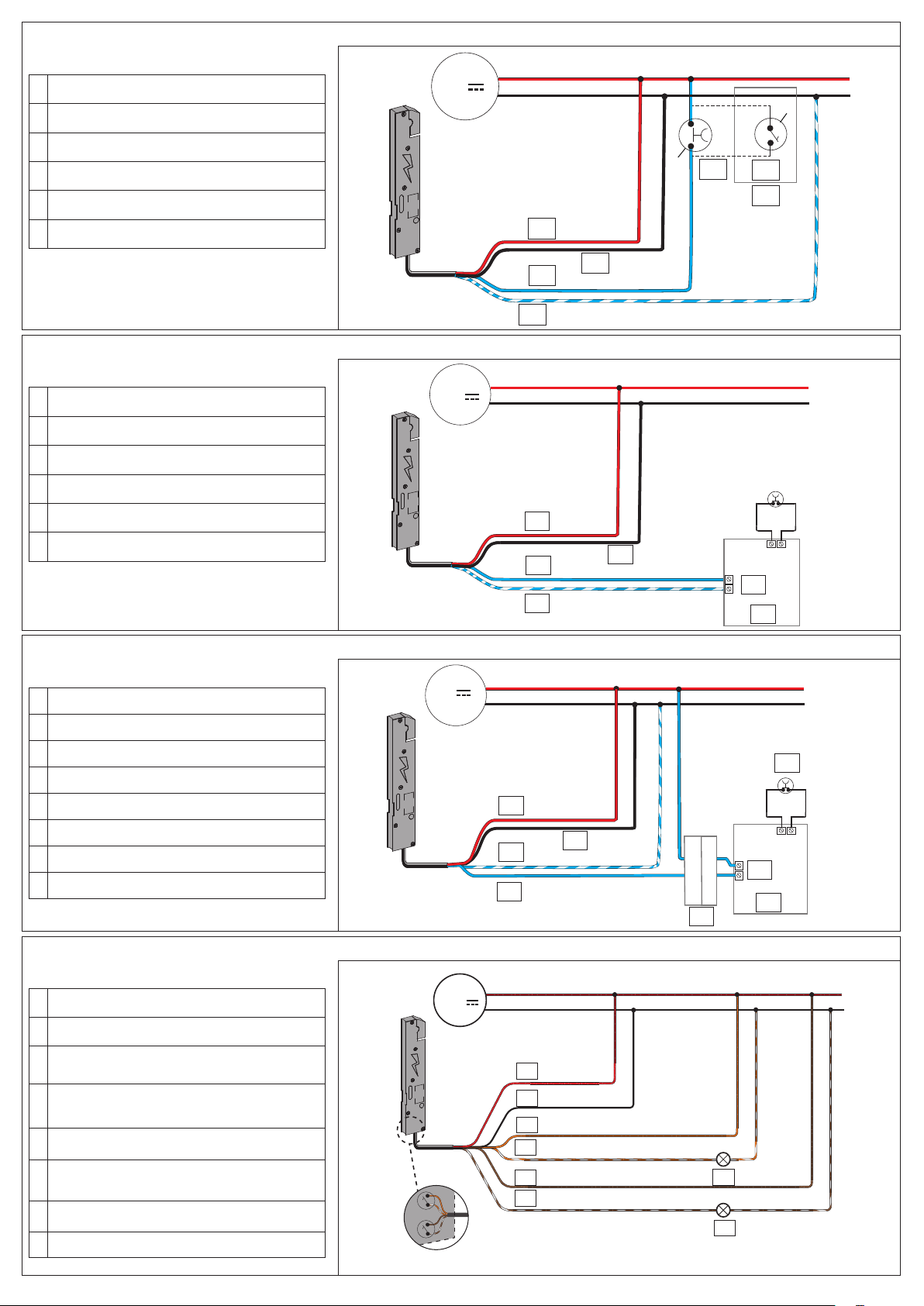
WARNING:
The electric current produced by some applications can be high, keeping the lock open even after the opening button has been
released. It is advisable to interface the input command with a repeater relay and connect the motor as shown in diagram 3.
WARNING: POWER FAILURE
If there is a power failure, the panic exit device will always revert to locked when power is restored.
INTERFACING FOR PANIC EXIT DEVICE STATUS
(example of installation with an actuator to open and close the door)
OUT1 and OUT2 outputs can be used to remotely control the status of the panic exit device.
OUT1 output is activated when the panic exit device is locked (latchbolt and lock engaged).
OUT2 output is activated when the panic exit device is completely open (latchbolt and lock withdrawn).
IMPORTANT: Both the outputs are free contacts normally open (C, NO) with a maximum capacity of 60V, 0.5mA
WARNING:
Connect devices with a maximum current absorption of 0.5A and a maximum voltage of 60V.
CISA declines all responsibility for the compliance of third-party devices used.
It is possible to connect 12V lights (see the accessories) directly to the lock power supply. Respect the polarity (+/-) of the lights/LEDs.
A repeater relay (item 1.07022.20.0) is needed to control locks, electric strike coils or 230V devices.